A bridge expansion joint structure

A technology for expansion joints and bridges, applied in bridges, bridge materials, bridge construction, etc., can solve problems affecting driving speed, comfort and safety, inability to inspect and maintain expansion joints, and insufficient firmness of the structure, etc., to achieve good bearing capacity, Satisfy the effects of stretching and deformation, stronger structure

Inactive Publication Date: 2019-07-19
湖南鸿路建设工程有限公司
View PDF4 Cites 0 Cited by
  • Summary
  • Abstract
  • Description
  • Claims
  • Application Information

AI Technical Summary

Problems solved by technology

Once the bridge expansion joints are destroyed, it will seriously affect the speed, comfort and safety of driving, and even cause driving safety accidents
[0003] However, the structure of the current bridge expansion joints is not strong enough, and there are potential safety hazards when vehicles pass by for a long time; moreover, the connection of expansion joints is now simply connected by steel plates, and this construction method is often directly made of steel plates to save trouble. Fixed connection, neither detachable connection, routine inspection and maintenance of expansion joints in daily use, there are potential safety hazards; and because the steel plate is relatively hard, the expansion joints connected by steel plates have poor driving comfort, and the driving process Car jumping is prone to occur in the middle, so it is of practical significance to design a durable expansion joint structure with good bearing capacity, good stability, and meeting the expansion and contraction deformation of the bridge.

Method used


Image

  • A bridge expansion joint structure
  • A bridge expansion joint structure
  • A bridge expansion joint structure

Examples


Embodiment

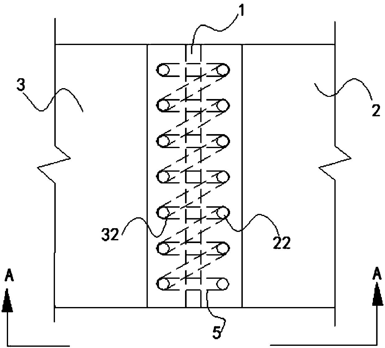
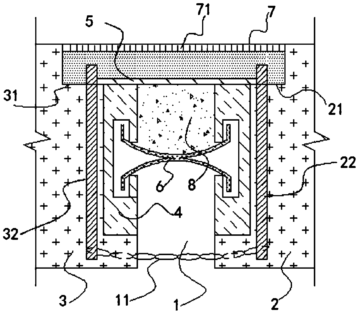
[0037] Embodiment: a kind of bridge expansion joint structure, as Figure 1-Figure 7, including a bridge body and an expansion joint 1, the expansion joint is located at one end of the bridge body, the expansion joint divides the bridge body into a first bridge body 2 and a second bridge body 3, the first bridge body is close to the expansion joint One end of the seam is concave to form a first supporting step 21, and the end of the first supporting step away from the expansion joint is equidistantly provided with a plurality of first fixing columns 22 distributed along the width direction of the bridge main body, and the first fixing columns Perpendicular to the bridge main body, one end of the second bridge main body close to the expansion joint is recessed to form a second supporting step 31, the second supporting step is flush with the first supporting step, and the first supporting step is The end of the two supporting steps away from the expansion joint is equidistantly ...


PUM

PropertyMeasurementUnit
thicknessaaaaaaaaaa

Abstract

Provided is a bridge expansion joint structure, comprising a bridge body (2, 3) and an expansion joint (1). The expansion joint (1) divides the bridge body (2, 3) into a first bridge body (2) and a second bridge body (3). A first bearing step (21) is formed on the first bridge body (2), and the first bearing step (21) is provided with a first fixed pillar (22). A second bearing step (31) is formed on the second bridge body (3), and the second bearing step (31) is provided with a second fixed pillar (32). Lateral faces of the first and second bearing steps (21, 31) are respectively fixedly connected to a C-shaped steel plate (4). An expansion joint connector (6) is provided between the first bridge body (2) and the second bridge body (3). The expansion joint connector (6) comprises an upper bearing body (61) and a lower supporting body (62), and the upper bearing body (61) and the lower supporting body (62) are both provided with reinforcing ribs (63). A cover plate (7) is provided above the expansion joint (1). Elastic filling materials (8) are filled between the expansion joint (1) and the expansion joint connector (6). The bridge expansion joint structure meets the requirement of road expansion deformation, is structurally secure, has a good bearing capacity, provides a good smooth and comfortable sensation during driving, and is also easy and convenient to install, inspect and maintain.

Description

technical field [0001] The invention belongs to the technical field of road engineering, and in particular relates to a bridge expansion joint structure. Background technique [0002] With the continuous development of society and the rapid development of our country's economy, roads, as the lifeblood of the country, have also achieved unprecedented development. Expansion joints are set at the junction of the bridge and the junction of the roads at both ends to meet the requirements of the deformation of the bridge deck. Usually, expansion joints are set between the two girder ends, between the girder end and the abutment, or at the hinged position of the bridge. The expansion joints are required to be free to expand and contract in two directions parallel and perpendicular to the bridge axis, firm and reliable, and the vehicles should run smoothly without sudden jumps and noises; installation, inspection, maintenance, and removal of dirt should be simple and convenient. On...

Claims


Application Information

Patent Timeline
Patent Type & Authority Patents(China)
IPC IPC(8): E01D19/06E01D101/40E01D101/30
CPCE01D19/06E01D19/065E01D2101/30E01D2101/40
Inventor 刘西平邹诚杰
Owner 湖南鸿路建设工程有限公司
Why Eureka
Try Eureka