
A hidden telescopic device at the bridge abutment and its construction method

A telescopic device and abutment technology, applied in bridges, bridge parts, bridge construction, etc., can solve the problems of increased impact of heavy vehicles, impact on service life, application limitations, etc., and achieve low investment in construction costs, reasonable design, and simple structure. Effect

Inactive Publication Date: 2016-05-25
XIAN HIGHWAY INST
View PDF9 Cites 0 Cited by
  • Summary
  • Abstract
  • Description
  • Claims
  • Application Information

AI Technical Summary

Problems solved by technology

The expansion device is the weakest link in the bridge structure. Since the expansion device directly bears the impact of repeated loads on the wheels, even if there is a small unevenness, it will be subjected to a large impact under the load of the vehicle, so it is also Most vulnerable to damage requiring repair and replacement
Slight defects and deficiencies in design or construction will lead to early damage, which not only directly makes bridge passers-by feel uncomfortable and lacks a sense of security, but sometimes also affects the normal use of the bridge structure itself
The reason for the general damage of the expansion device is that in addition to the increase in traffic flow and the increase in heavy vehicles (the impact effect is significantly increased), the design, construction and maintenance cannot be ignored. Moreover, the bridge deck has a sudden change in stiffness at the position of the expansion joint, and it is traveling at a high speed. Under the repeated action of vehicle load, its service life is seriously affected
Therefore, the vulnerability of bridge telescopic devices has always been a major problem in road traffic
But at present, the research on seamless structure is still in its infancy, with few structural forms and limited application.

Method used


Image

  • A hidden telescopic device at the bridge abutment and its construction method
  • A hidden telescopic device at the bridge abutment and its construction method
  • A hidden telescopic device at the bridge abutment and its construction method

Examples


Embodiment Construction

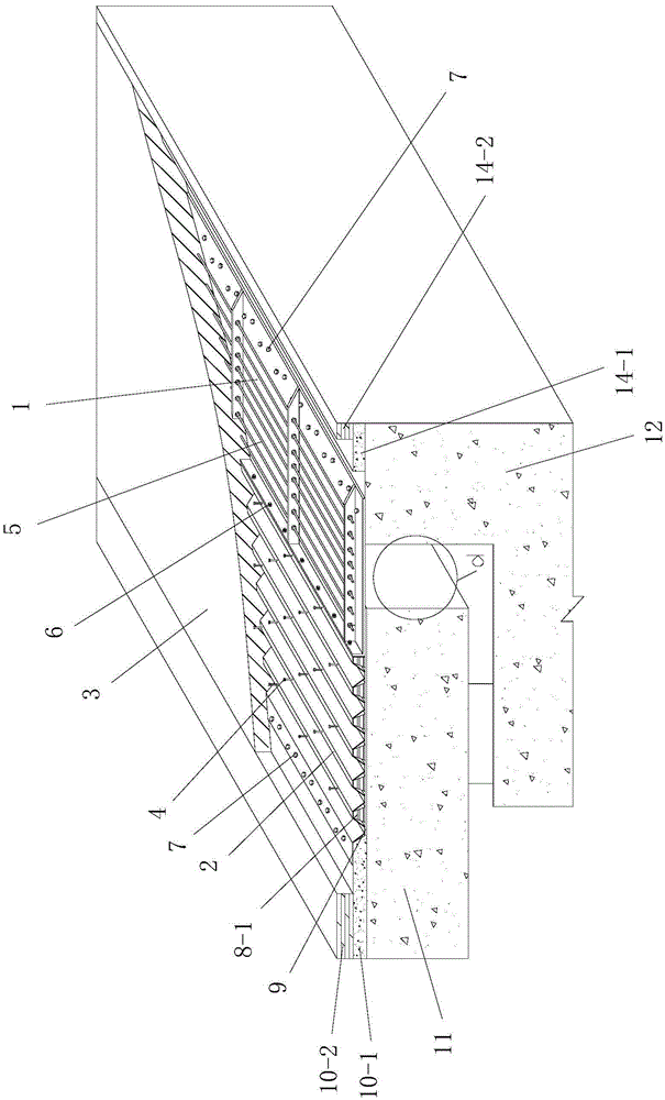
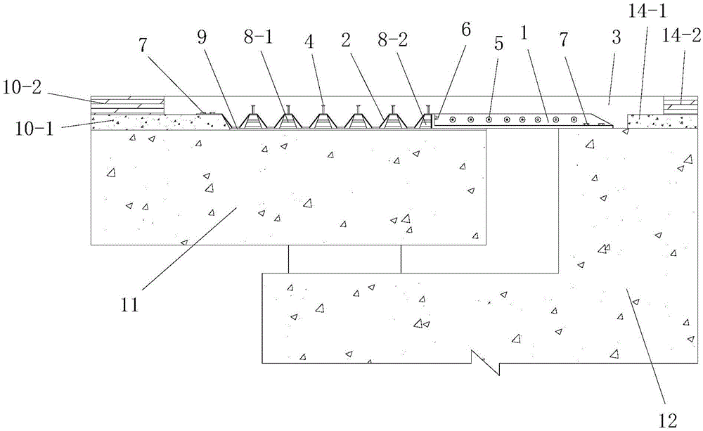
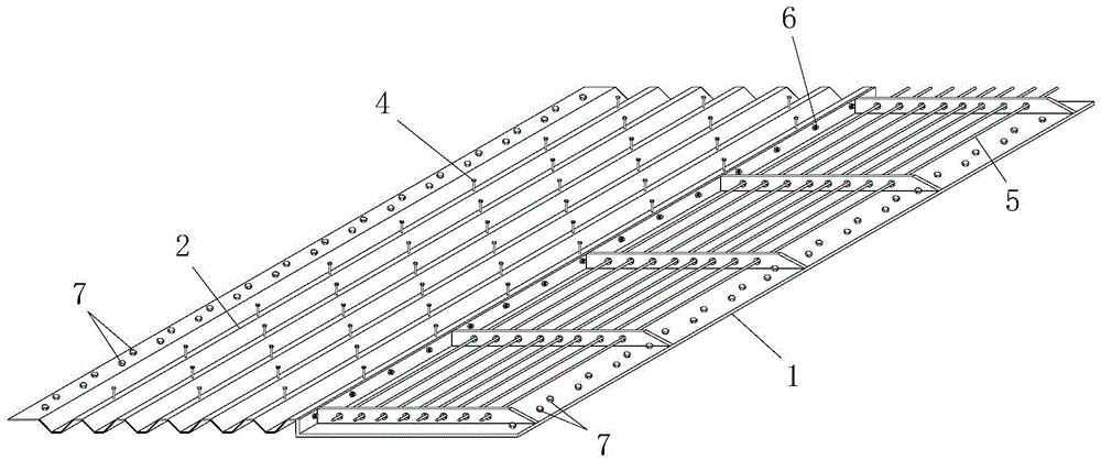
[0075] Such as figure 1 , figure 2 and image 3 The shown hidden expansion device at the abutment includes a prefabricated expansion joint arranged on the abutment expansion joint of the constructed bridge and an expansion joint filling layer 3 filled above the prefabricated expansion joint. It is the expansion joint left between the main girder 11 and the abutment 12 of the bridge being constructed; the bridge deck pavement structure is laid on the main girder 11, and the pavement pavement is laid on the outer side of the upper part of the abutment 12 and its The inner side of the upper part is the exposed section of the abutment. A reserved installation groove for the installation of the prefabricated telescopic assembly is formed between the bridge deck pavement structure and the road pavement layer. The longitudinal bridge length of the reserved installation groove is greater than The distance between the main beam 11 and the abutment 12, the section of the main beam 11...


PUM


Abstract

The invention discloses an abutment hidden expansion device and a construction method thereof. The expansion device comprises a prefabricated expansion component arranged on an abutment expansion joint, and an expansion joint filler filling layer filled in the upper side of the prefabricated expansion component, wherein a bridge deck pavement structure is paved on a main beam; a slide layer is paved on an exposed section of the main beam; a road surface pavement layer is arranged at the outer side of the upper part of an abutment; the prefabricated expansion component comprises a reinforced joint plate and a waveform expansion plate; a construction method of an expansion device to be repaired comprises the steps of cleaning of an original bridge expansion device, construction of a reversed mounting groove, construction of the slide layer, field assembly and installation of the prefabricated expansion component and construction of the expansion joint filler filling layer; and a construction method of an expansion device to be constructed comprises the steps of prefabrication of the prefabricated expansion component, field assembly of the prefabricated expansion component, construction of the slide layer, installation of the prefabricated expansion component and construction of the bridge deck pavement structure and the expansion joint filler filling layer. The abutment hidden expansion device and the construction method thereof have the advantages of reasonable design, convenience for construction and good use effect, and can solve multiple problems in traditional expansion devices.

Description

technical field [0001] The invention belongs to the technical field of bridge expansion joint construction, and in particular relates to a hidden expansion device at an abutment and a construction method thereof. Background technique [0002] The bridge expansion device is a device installed at the expansion joint of the bridge deck in order to make the vehicle pass through the bridge deck smoothly and meet the needs of the bridge deck deformation. The expansion device is the weakest link in the bridge structure. Since the expansion device directly bears the impact of repeated loads on the wheels, even if there is a small unevenness, it will be subjected to a large impact under the load of the vehicle, so it is also The most vulnerable to damage and need repair replacement. Slight defects and deficiencies in design or construction will lead to early damage, which not only directly makes bridge passers-by feel uncomfortable and lacks a sense of security, but sometimes also a...

Claims


Application Information

Patent Timeline
Patent Type & Authority Patents(China)
IPC IPC(8): E01D19/06E01D21/00E01C7/32
CPCE01D19/06E01D21/00
Inventor 袁卓亚王卫山陈军刘永健王旭杜进生蒲广宁宋彬侯登峰石雄伟高诣民舒涛
Owner XIAN HIGHWAY INST
Learn More