Tool for detecting airtightness of engine cylinder cover

A technology of air tightness detection and engine cylinder head, which is applied in the direction of fluid tightness test, measuring device, liquid tightness measurement using liquid/vacuum degree, etc. It can solve the leakage of plugging position, the error of detection result and the stability of detection Poor performance and other problems, to achieve the effect of accurate detection of cylinder head air tightness, high sealing performance, and not easy to shift

Active Publication Date: 2018-06-12
宁波强盛机械模具有限公司
View PDF5 Cites 7 Cited by
  • Summary
  • Abstract
  • Description
  • Claims
  • Application Information

AI Technical Summary

Problems solved by technology

The existing cylinder head generally has through holes on the top and left and right sides of the cylinder head, so in the general inspection process, the cylinder head is usually fixed manually first, and then each air hole on the cylinder head is sealed with a plug. plugging, and then inflate through any through hole to detect the air tightness of the inner wall chamber of the cylinder head. The efficiency of this one-by-one plugging method is low, and the detection stability is poor, which will lead to errors in the detection results, and the existing plugging structure Usually, the ejector rod is directly fixed against the side wall of the cylinder head through hole. If the positioning of the cylinder head is not accurate enough in this way, the sealing of the through hole on the cylinder head will not be tight enough, and leakage will occur at the sealing position.

Method used


Image

  • Tool for detecting airtightness of engine cylinder cover
  • Tool for detecting airtightness of engine cylinder cover
  • Tool for detecting airtightness of engine cylinder cover

Examples


Embodiment Construction

[0025] The present invention will be further described below in conjunction with the accompanying drawings and specific embodiments.

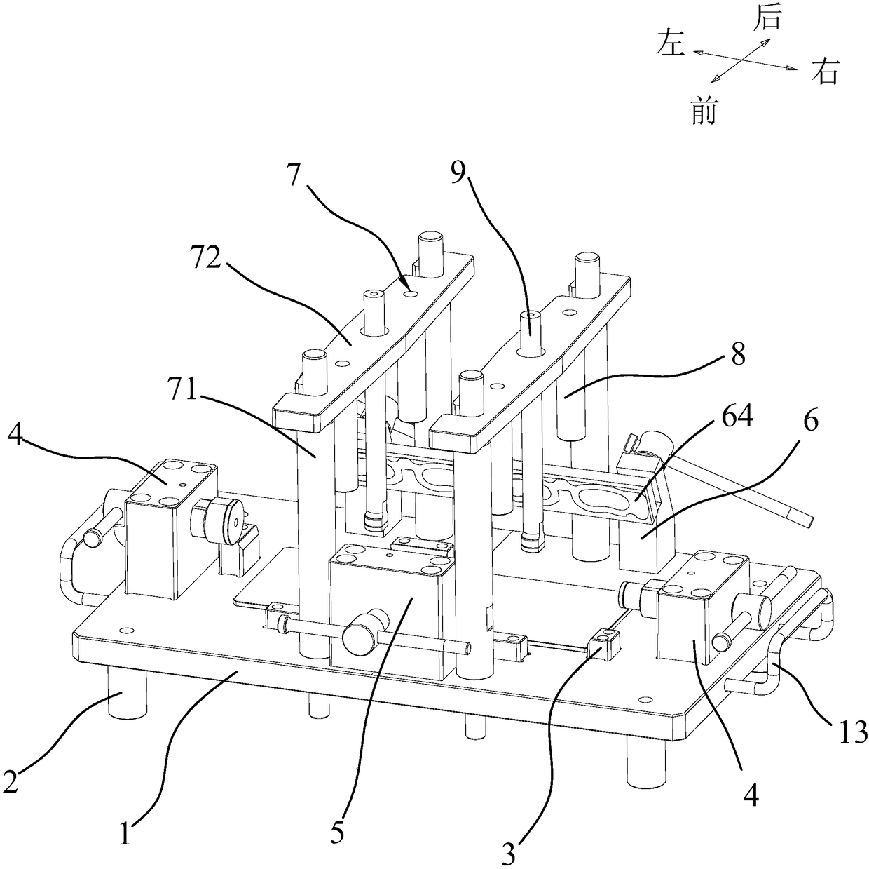
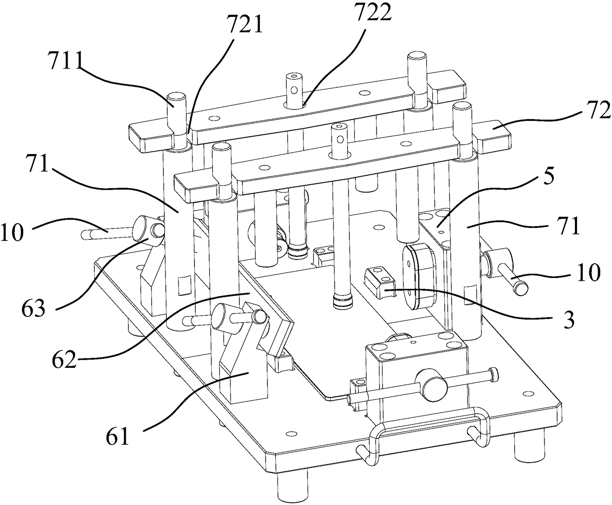
[0026] Such as Figure 1-7 As shown, the present invention provides an engine cylinder head air tightness detection tool, including a base plate 1, a plurality of support feet 2 are provided at the bottom of the base plate 1, and a plurality of positioning pins for positioning and placing the cylinder head 100 are provided on the base plate 1. Block 3, this positioning block 3 can be a rubber block or a metal block, and then a layer of rubber gasket is bonded on the upper surface of the metal block to ensure that the outer surface of the engine cylinder head is not damaged.

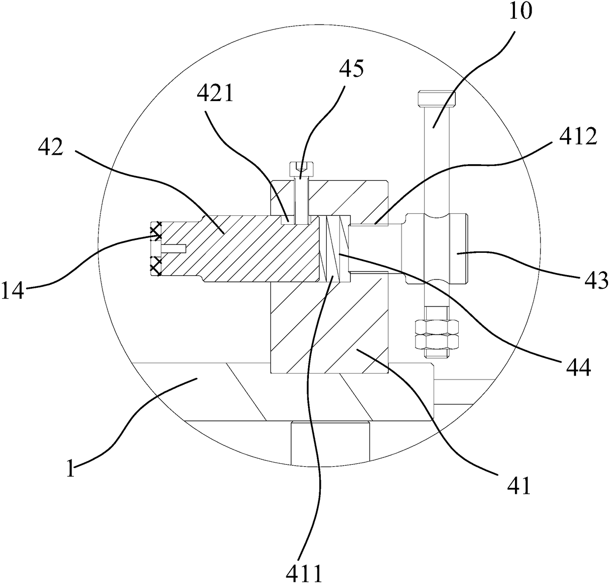
[0027] The left and right sides of the bottom plate 1 are respectively provided with a first plugging device 4 for plugging the air holes on both sides of the cylinder head 100. The head 42 is provided with an air inlet 422 for charging air into the cylinder head 100 to b...


PUM


Abstract

The invention discloses a tool for detecting the airtightness of an engine cylinder cover, and the tool comprises a bottom plate. The bottom of the bottom plate is provided with a plurality of supportlegs, and the bottom plate is provided with a plurality of positioning blocks which are used for locating a placed cylinder cover. The left and right sides of the bottom plate are respectively provided with first sealing devices which are used for sealing the air holes at two sides of the cylinder cover. The front and back sides of the bottom plate are also respectively provided with a first compression apparatus and a second compression apparatus which are used for compressing the cylinder cover in a longitudinal direction. The bottom plate is provided with two fixed supports in the lateraldirection, and the two fixed supports are respectively provided with an upper pressure rod for vertically pressing the cylinder cover, and a second sealing device for sealing the air holes at the upper part of the cylinder cover. According to the invention, the tool is stable in positioning of the cylinder cover, and the sealing devices can achieve the buffering and adjustment, thereby effectivelyimproving the sealing performances of a through hole.

Description

technical field [0001] The invention relates to the technical field of engines, in particular to an engine cylinder head airtightness detection tool. Background technique [0002] In the automobile engine structure, the engine cylinder head belongs to the valve mechanism, which is mainly used to close the upper part of the engine cylinder and form the combustion chamber. At the same time, it also acts as a seal to prevent engine oil from leaking, so that the engine can be lubricated normally. [0003] Therefore, in the production process of the cylinder head, air tightness testing is a very important and critical step. The existing cylinder head generally has through holes on the top and left and right sides of the cylinder head, so in the general inspection process, the cylinder head is usually fixed manually first, and then each air hole on the cylinder head is sealed with a plug. plugging, and then inflate through any through hole to detect the air tightness of the inner...

Claims


Application Information

Patent Timeline
Patent Type & Authority Applications(China)
IPC IPC(8): G01M3/02
CPCG01M3/025
Inventor 耿前程
Owner 宁波强盛机械模具有限公司
Why Eureka
Try Eureka