Multi-station camshaft press

A technology of camshafts and press-fitting machines, which is applied to assembly machines, metal processing, and tool manufacturing, and can solve the problems of wasted manpower and time, and large bump damage of camshafts, so as to achieve a simple and convenient overall layout and reduce bumps and damages , Improve the effect of assembly quality and efficiency

Pending Publication Date: 2019-10-08
淮安辰锟科技有限公司
View PDF1 Cites 5 Cited by
  • Summary
  • Abstract
  • Description
  • Claims
  • Application Information

AI Technical Summary

Problems solved by technology

However, in the process of frequently switching equipment for assembly of the camshaft, the probability of the camshaft being bumped and damaged is relatively high, and a lot of labor and time are wasted in this process. How to further improve the automation capability of the equipment is an important problem

Method used


Image

  • Multi-station camshaft press
  • Multi-station camshaft press
  • Multi-station camshaft press

Examples


Embodiment 1

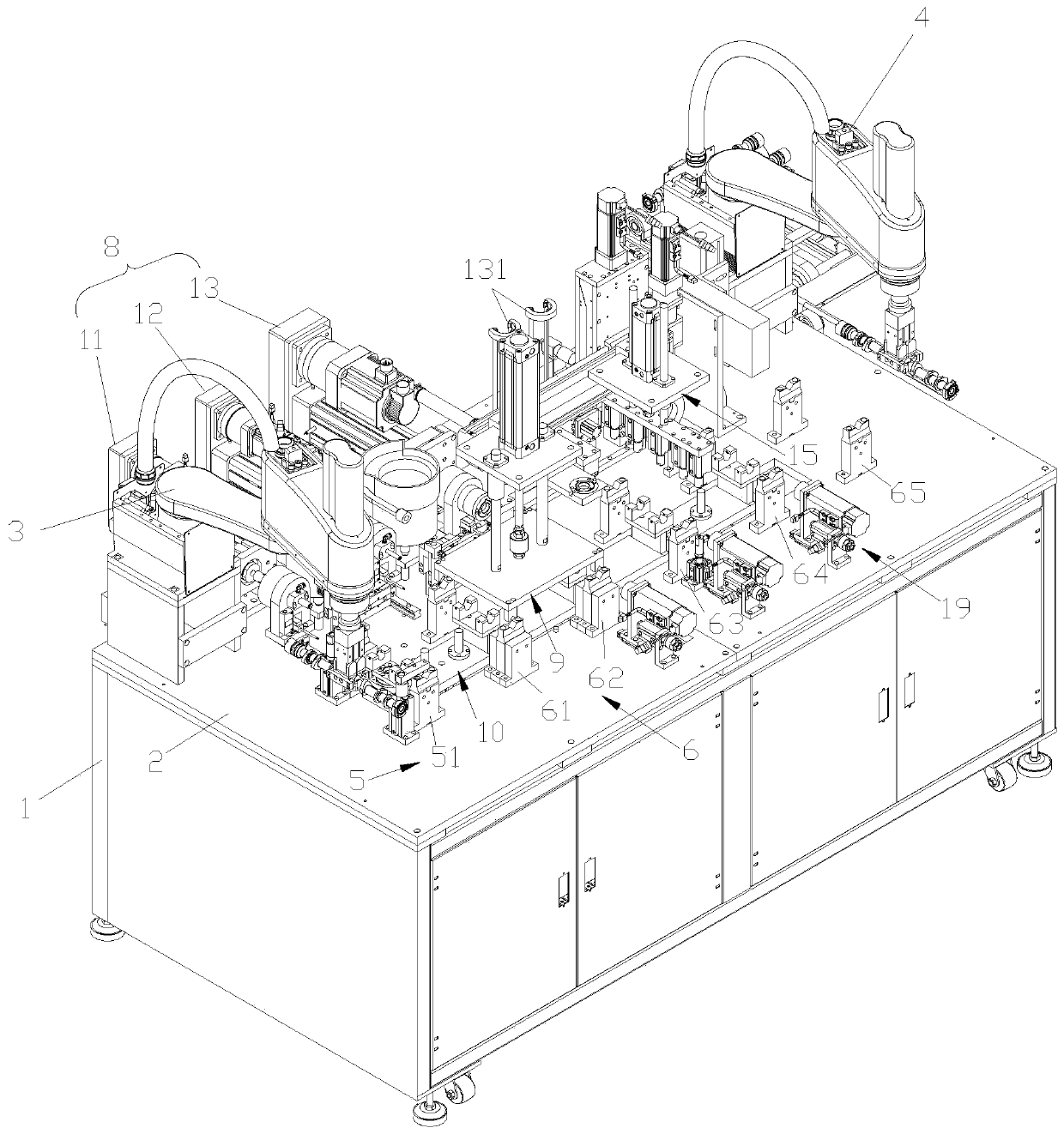
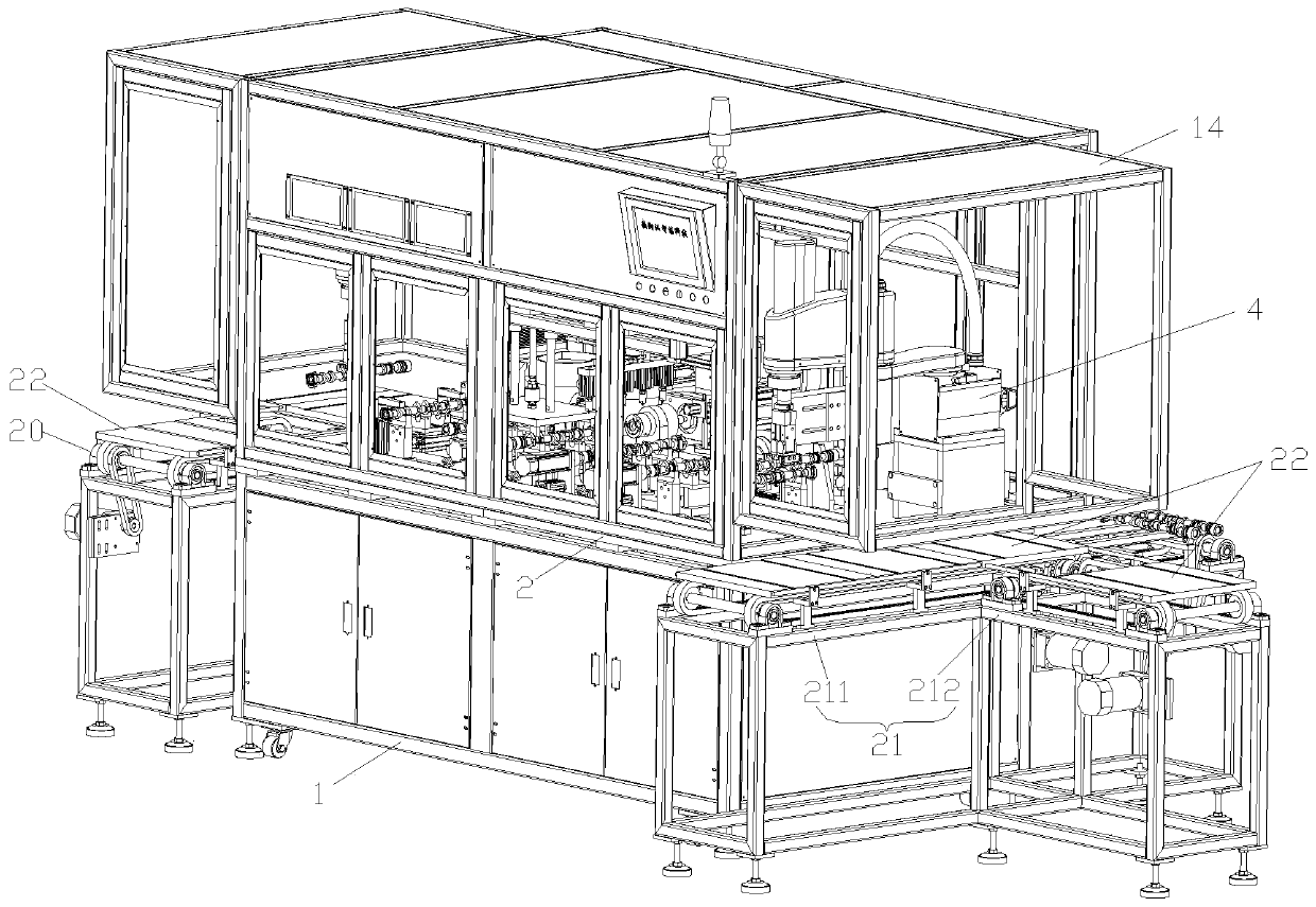
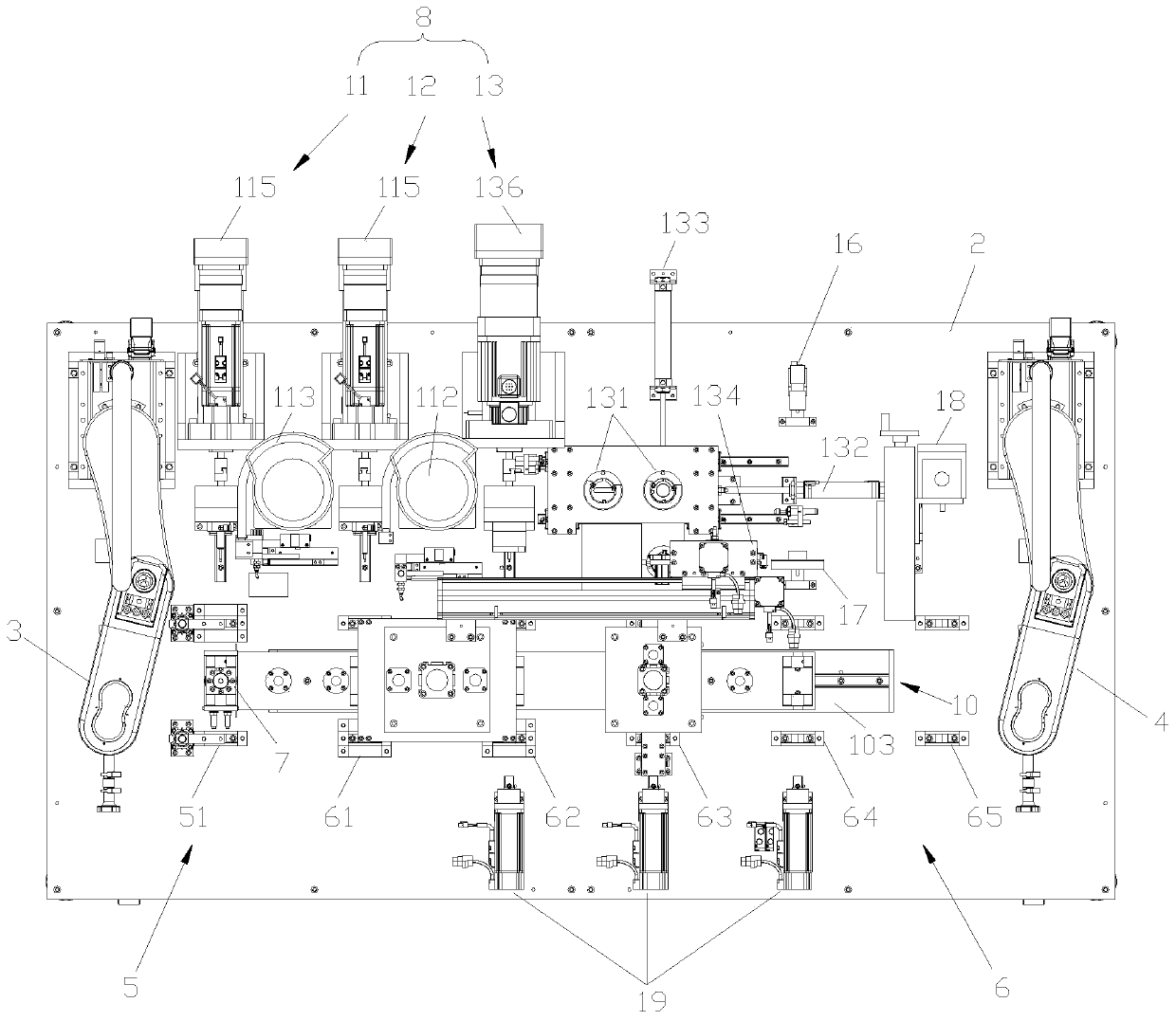
[0034] Embodiment 1 of the present invention: a multi-station camshaft press-fitting machine, constituted as Figure 1 to Figure 9 shown, see Figure 1 to Figure 3 , comprising a frame 1, the frame 1 is provided with a work platform 2, the two ends of the work platform 2 are respectively provided with a loading manipulator 3 and a material unloading manipulator 4, and the middle of the work platform 2 is sequentially provided with a sequencer Bit group 5 and reverse installation station group 6, a steering mechanism 7 is arranged between the forward installation station group 5 and the reverse installation station group 6, the forward installation station group 5 and the reverse installation station group 6 rows An assembly device 8 is provided on the same side of the fabric direction, a workpiece clamping device 9 is also provided on the forward assembly station group 5 and reverse assembly station group 6, and a workpiece overall displacement device 10 is also provided on th...

Embodiment 2

[0049] Embodiment 2: A kind of multi-station camshaft press-fitting machine, constitutes as Figure 1 to Figure 9 shown, see Figure 1 to Figure 3 , comprising a frame 1, the frame 1 is provided with a work platform 2, the two ends of the work platform 2 are respectively provided with a loading manipulator 3 and a material unloading manipulator 4, and the middle of the work platform 2 is sequentially provided with a sequencer Bit group 5 and reverse installation station group 6, a steering mechanism 7 is arranged between the forward installation station group 5 and the reverse installation station group 6, the forward installation station group 5 and the reverse installation station group 6 rows An assembly device 8 is provided on the same side of the fabric direction, a workpiece clamping device 9 is also provided on the forward assembly station group 5 and reverse assembly station group 6, and a workpiece overall displacement device 10 is also provided on the working platfor...


PUM


Abstract

The invention relates to the technical field of camshaft assembly, in particular to a multi-station camshaft press. The multi-station camshaft press comprises a rack, wherein a working platform is arranged on the rack; a feeding manipulator and a discharging manipulator are respectively arranged at two ends of the working platform; a forward assembling station group and a backward assembling station group are sequentially arranged in the middle of the working platform; a steering mechanism is arranged between the forward assembling station group and the backward assembling station group; an assembling device is arranged on the same side of the distributing directions of the forward assembling station group and the backward assembling station group; workpiece clamping devices are arranged on the forward assembling station group and the backward assembling station group; and a workpiece integral displacing device is also arranged on the working platform. The multi-station camshaft presshas the advantages that multi-station assembly of a camshaft is realized, the integrating and automatic abilities of equipment are enhanced, the waste of human power, material resources and time for assembly by frequent switching of equipment through the camshaft is reduced, bump and damage to assembly of the camshaft due to frequent switching of the equipment are also reduced, and the assemblingquality and the assembling efficiency of the camshaft are improved.

Description

technical field [0001] The invention relates to the technical field of camshaft assembly, in particular to a multi-station camshaft pressing machine. Background technique [0002] The camshaft is a key component of the engine's valve system. It plays an important role in transmitting torque. It can drive the opening and closing of the intake and exhaust valves according to the valve requirements, affecting the performance of the entire engine. During the assembly process of the camshaft, parts and materials including bowl plugs, steel balls and signal wheels need to be loaded at both ends. At present, the installation method still involves manual knocking, which is time-consuming and labor-intensive. The more common installation method is to The camshaft is assembled by several press-fitting equipment according to the process, as shown in the patent publication number CN207735883U, which ensures the speed and quality of parts assembly compared to manual assembly. However, i...

Claims


Application Information

Patent Timeline
Patent Type & Authority Applications(China)
IPC IPC(8): B23P21/00
CPCB23P19/001B23P19/006B23P19/007B23P21/004
Inventor 朱微
Owner 淮安辰锟科技有限公司
Why Eureka
Try Eureka