Bridge anti-collision guardrail

A technology for anti-collision guardrails and bridges, which is applied in the direction of bridges, bridge parts, bridge construction, etc., which can solve the problems of not being able to better protect bridges and vehicles, not being able to break through, pass under, overturn bridges, and damage to vehicle bridges, etc., to achieve Suitable for popularization, convenient construction, and the effect of protecting personnel

Inactive Publication Date: 2018-06-15
PINGDINGSHAN HIGHWAY ENG
View PDF5 Cites 9 Cited by
  • Summary
  • Abstract
  • Description
  • Claims
  • Application Information

AI Technical Summary

Problems solved by technology

[0002] Bridge guardrail refers to the guardrail set on the bridge. Its purpose is to prevent out-of-control vehicles from getting out of the bridge. Highway grade, comprehensive consideration of its safety, coordination, characteristics of objects to be protected and on-site geometric conditions to determine the anti-collision grade, and then select the structural form according to its own structure, economy, construction and maintenance and other factors, the other There are three ways to embed the column directly, the flange connection type, and the bridge guardrail and the bridge deck through the force-transmitting steel bar. When conditions permit, the removable guardrail can be used, but the current guardrail is in the When a vehicle collides, it generally bears the impact directly, causing the guardrail to bend, deform or even break. This direct impact will cause serious damage to the vehicle and the bridge, and the bridge and vehicle cannot be better protected to ensure the safety of pedestrians. Therefore, we propose a bridge crash barrier to solve the above problems

Method used


Image

  • Bridge anti-collision guardrail
  • Bridge anti-collision guardrail
  • Bridge anti-collision guardrail

Examples


Embodiment Construction

[0021] The following will clearly and completely describe the technical solutions in the embodiments of the present invention with reference to the accompanying drawings in the embodiments of the present invention. Obviously, the described embodiments are only some, not all, embodiments of the present invention.

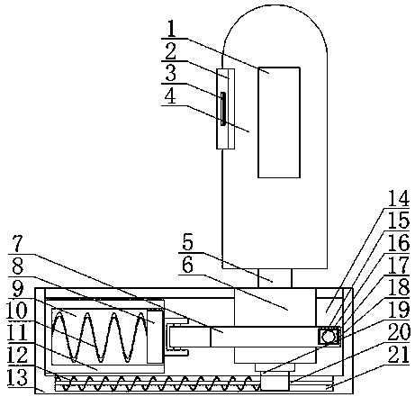
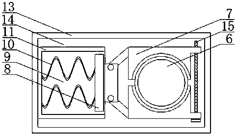
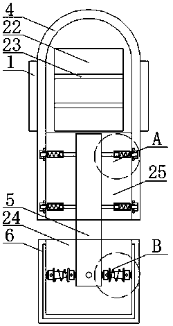
[0022] refer to Figure 1-5 , a bridge anti-collision guardrail, comprising a base 13, the upper end of the base 13 is provided with a placement groove 14, and the bottom of the placement groove 14 is provided with a transverse damping device for lateral buffering to prevent vehicles from rushing out of the bridge, and the transverse damping device The upper end is provided with a mounting block 6, and a clamping device is provided on the mounting block 6, which is convenient for clamping replacement, and one end of the clamping device is fixedly connected on the side wall of one end in the placement groove 14, and the upper end of the mounting block 6 is provided wit...


PUM


Abstract

The invention discloses a bridge anti-collision guardrail which comprises a base. A placement groove is formed in the upper end of the base. A transverse damping device is arranged at the bottom inside a placement groove, an installing block is arranged at the upper end of the transverse damping device, a clamping device is arranged on the installing block, and one end of the clamping device is fixedly connected to the side wall of one end inside the placement groove. Impact force generated during automobile collision can be converted and offset, the influence caused by automobile collision toa bridge is eliminated, the safety of pedestrians is ensured as much as possible, by combining a vertical rod, a roller, a compression resistance spring and a cross rod, the vertical rod can rotate and deflect during automobile collision so as to resolve the impact force generated by the borne collision, the vertical rod does not need to bear the collision directly, the influence generated by thecollision to the bridge and automobiles is effectively lowered, persons inside automobiles are better protected, the automobiles are made to deflect, it is ensured that the automobiles cannot directly rush out of the bridge, and the guardrail is simple in structure, convenient to operate and suitable for being popularized.

Description

technical field [0001] The invention relates to the technical field of bridge guardrails, in particular to a bridge anti-collision guardrail. Background technique [0002] Bridge guardrail refers to the guardrail set on the bridge. Its purpose is to prevent out-of-control vehicles from getting out of the bridge. Highway grade, comprehensive consideration of its safety, coordination, characteristics of objects to be protected and on-site geometric conditions to determine the anti-collision grade, and then select the structural form according to its own structure, economy, construction and maintenance and other factors, the other There are three ways to embed the column directly, the flange connection type, and the bridge guardrail and the bridge deck through the force-transmitting steel bar. When conditions permit, the removable guardrail can be used, but the current guardrail is in the When a vehicle collides, it generally bears the impact directly, causing the guardrail to...

Claims


Application Information

Patent Timeline
Patent Type & Authority Applications(China)
IPC IPC(8): E01D19/10
CPCE01D19/103
Inventor 李彦龙陈国亮李勋董红磊李伟周建鹏韩国耀黄贵松彭祖胜刘卫献王永见韩玉枝王光辉王跃斌李静杨平刚闫小峰陈政任陈旭朦王智慧吕晓航尤国岭张建军宋旭慧王磊薛磊何佳毅郭树朋谢飞周宏博王国杰上官海辽董锡琴苗青河尹红涛孙长远何方芳
Owner PINGDINGSHAN HIGHWAY ENG
Why Eureka
Try Eureka