Fast excavation equipment and excavation method for foundation pits

A foundation pit, fast technology, applied in excavation, infrastructure engineering, earth mover / excavator, etc., can solve problems such as unfavorable interests, hidden dangers, low efficiency of manual excavation, etc., to expand the scope of excavation, improve The effect of excavation efficiency

Inactive Publication Date: 2018-06-15
广东朝立建筑科技有限公司
View PDF7 Cites 4 Cited by
  • Summary
  • Abstract
  • Description
  • Claims
  • Application Information

AI Technical Summary

Problems solved by technology

[0002] The foundation pit is an earth pit excavated at the foundation design position according to the base elevation and foundation plane size. If the excavation is not deep, you can use the method of setting the side slope to stabilize the soil slope. The slope size is determined according to the relevant construction regulations. The foundation pit even adopts methods such as underground diaphragm wall and column-type bored pile interlocking to protect the outer soil layer from collapsing. There is no influence on nearby buildings. The well point method can be used to reduce the groundwater level. Natural air-conditioning freezing method can be used for excavation, etc. Excavators are generally used for excavation of foundation pits, and some positions cannot be reached by excavators, and manual excavation will be used instead, but manual excavation is inefficient and has many problems. Big potential safety hazard, not conducive to the interests of the enterprise itself

Method used


Image

  • Fast excavation equipment and excavation method for foundation pits
  • Fast excavation equipment and excavation method for foundation pits

Examples


Embodiment Construction

[0022] The following will clearly and completely describe the technical solutions in the embodiments of the present invention with reference to the accompanying drawings in the embodiments of the present invention. Obviously, the described embodiments are only some, not all, embodiments of the present invention. Based on the embodiments of the present invention, all other embodiments obtained by persons of ordinary skill in the art without making creative efforts belong to the protection scope of the present invention.

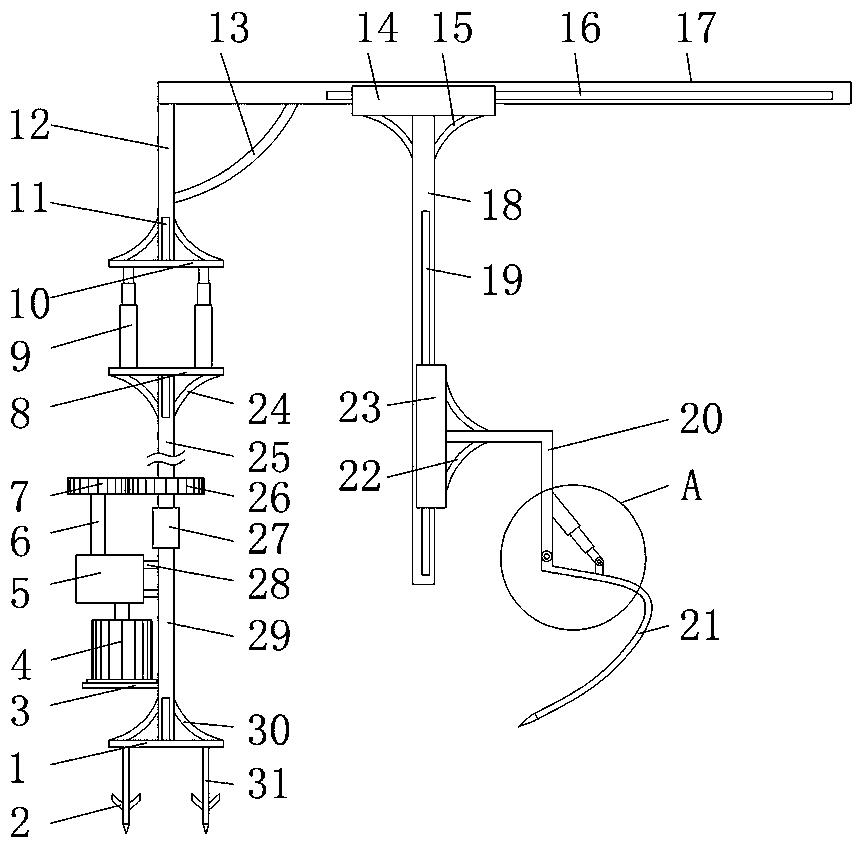
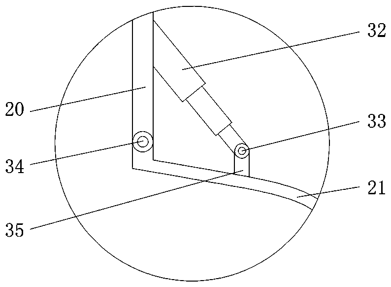
[0023] see Figure 1-2 , a foundation pit rapid excavation equipment and excavation method, comprising a first support plate 1, anchor rods 31 are fixedly connected around the bottom of the first support plate 1, and the outer surface of the anchor rod 31 is fixedly connected with barbs 2 , the middle end of the top of the first support plate 1 is fixedly connected with the first support rod 29, and the lower end of the left side of the first support rod 29 is...


PUM


Abstract

The invention discloses fast excavation equipment and excavation method for foundation pits. The fast excavation equipment comprises a first support plate. Anchor rods are fixedly connected to the periphery of the bottom of the first support plate, and barbs are fixedly connected to the outer surfaces of the anchor rods. A first support rod is fixedly connected to the middle end of the top of thefirst support plate, and a motor support is fixedly connected to the lower end of the left side of the first support rod. According to the fast excavation equipment and excavation method for the foundation pits, the motor support is fixedly connected to the lower end of the left side of the first support rod; under the effects of a motor, a speed changing box, a transmission rod, a driving gear disc, a bearing seat and a driven gear disc, the requirement of people for horizontally rotating a first sliding rod can be met; the excavation range is effectively widened; by means of an first electric extending-and-contracting rod, the requirement of people for adjusting the vertical height of the first sliding rod can be met, and the requirement of people for excavating the foundation pits at different depth is met; and meanwhile, by means of a first sliding groove, a first slider, a second sliding groove and a second slider, the requirement of people for excavating the foundation pits flexibly can be met.

Description

technical field [0001] The invention relates to the technical field of foundation pit excavation, in particular to a rapid foundation pit excavation equipment and an excavation method. Background technique [0002] The foundation pit is an earth pit excavated at the foundation design position according to the base elevation and foundation plane size. If the excavation is not deep, you can use the method of setting the side slope to stabilize the soil slope. The slope size is determined according to the relevant construction regulations. The foundation pit even adopts methods such as underground diaphragm wall and column-type bored pile interlocking to protect the outer soil layer from collapsing. There is no influence on nearby buildings. The well point method can be used to reduce the groundwater level. Natural air-conditioning freezing method can be used for excavation, etc. Excavators are generally used for excavation of foundation pits, and some positions cannot be reac...

Claims


Application Information

Patent Timeline
IPC IPC(8): E02F5/00E02D17/02
CPCE02D17/02E02F5/00
Inventor 李炬
Owner 广东朝立建筑科技有限公司
Why Eureka
Try Eureka