
Hidden scenic spot for the tourist attraction

A hidden and scenic spot technology, applied in the field of hidden scenic spots, can solve the problems of single scenic spots, low tourist attraction, and poor aesthetics of scenic spots, so as to achieve the effect of improving mystery and enhancing attractiveness

Inactive Publication Date: 2018-06-15
萧县智鑫知识产权运营有限公司
View PDF0 Cites 0 Cited by
  • Summary
  • Abstract
  • Description
  • Claims
  • Application Information

AI Technical Summary

Problems solved by technology

[0003] The purpose of the present invention is to overcome the problems that most of the scenic spots in the existing tourist attractions are single, fixed structures, not attractive to tourists, and the aesthetics of the scenic spots are not good, and to provide an Good, hidden attractions for tourist attractions that can be hidden

Method used


Image

  • Hidden scenic spot for the tourist attraction
  • Hidden scenic spot for the tourist attraction
  • Hidden scenic spot for the tourist attraction

Examples


Embodiment 1

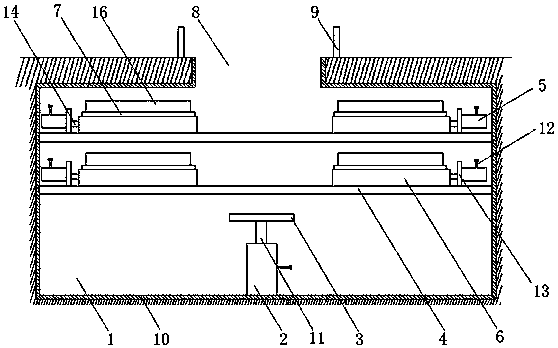
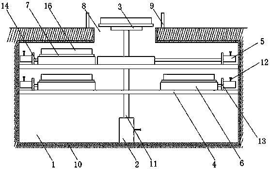
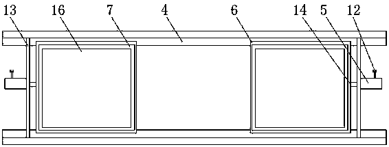
[0018] as attached Figure 1-4 As shown, a hidden scenic spot for a tourist attraction includes a bearing chamber 1, a cylinder one 2, a push plate 3, a slide rail 4, a cylinder two 5, a backing plate 6 and a bearing plate 7, and is characterized in that: The carrying chamber 1 is arranged below the ground, and a notch 8 is arranged on the top of the carrying chamber 1. The cylinder one 2 is arranged at the bottom of the carrying chamber 1, and a power cord 12 and a piston rod one 11 are arranged on the cylinder one 2. The push plate 3 is arranged on the piston rod one 11, the slide rail 4 is arranged in the carrying chamber 1, and a positioning plate 13 is arranged between the slide rail 4 and the slide rail 4, and the cylinder two 5 Be arranged on the positioning plate 13, and be provided with power line 12, piston rod 2 14 on cylinder two 5, described backing plate 6 is arranged between slide rail 4 and slide rail 4, and is provided with on backing plate 6 Fixing hole 15, ...

Embodiment 2

[0023] as attached Figure 5 As shown, a hidden scenic spot for a tourist attraction includes a bearing chamber 1, a cylinder one 2, a push plate 3, a slide rail 4, a cylinder two 5, a backing plate 6 and a bearing plate 7, and is characterized in that: The carrying chamber 1 is arranged below the ground, and a notch 8 is arranged on the top of the carrying chamber 1, and a motor 17 is arranged on the bottom of the carrying chamber 1. Connecting plate 19 is provided, and described cylinder one 2 is arranged on connecting plate 19, and is provided with power line 12, piston rod one 11 on cylinder one 2, and cylinder one 2, piston rod one 11 pushes push plate 3 upwards, After the push plate 3 passes through the fixing hole 15 on the backing plate 6, it continues to push the bearing plate 7 and the landscape platform 16 on the bearing plate 7 upwards, so that the landscape platform 16 rises from the notch 8, and the motor 17 drives the transmission shaft 18 to rotate. Transmissi...


PUM


Abstract

The invention discloses a hidden scenic spot for the tourist attraction, including a bearing chamber, a cylinder 1, a push plate, slide rails, a cylinder 2, a pad and a carrying plate, characterized in that the bearing chamber is set below ground and a rabbet is set at the top of the bearing chamber. The cylinder 1 is set at the bottom of the bearing c, and the push plate is set on the piston rod1, the rail is set up in the bearing chamber, the cylinder 2 is set on the positioning plate, the pad is set between the slide rails, and the mounting holes are set up on the pad. The bearing plates are set on the pad and have a landscape station set on the bearing plate. The present invention has a guard rail at the edge of the top rabbet of the chamber, and it has a waterproof layer on the interior walls of the bearing chamber, improving the safety of the scenic spot through the guardrail, avoiding the ingress of water or water in the soil through a waterproof layer, improving the safety ofthe cylinder 1 and the cylinder 2, and thus improving the security of scenic spots.

Description

technical field [0001] The invention relates to the field of tourist attractions, in particular to a hidden scenic spot used in tourist attractions. Background technique [0002] With the improvement of people's economic level, more and more people will travel to tourist attractions during holidays, but most of the existing tourist attractions are fixed and single-structured, which will cause visual fatigue to tourists after a long time, reducing the The attractiveness to tourists affects the income of tourist attractions. Contents of the invention [0003] The purpose of the present invention is to overcome the problems that most of the scenic spots in the existing tourist attractions are single, fixed structures, not attractive to tourists, and the aesthetics of the scenic spots are not good, and to provide an Good, hidden attractions for tourist attractions that can be hidden. [0004] The technical scheme that the technical problem that the present invention solves t...

Claims


Application Information

Patent Timeline
Patent Type & Authority Applications(China)
IPC IPC(8): E04H3/10
CPCE04H3/10
Inventor 吴义顺彭彬
Owner 萧县智鑫知识产权运营有限公司
Learn More