Push-pull type opening and closing box

A push-pull, switch technology, applied in the field of boxes with switches or locks, can solve the problem of not being attractive enough to the recipient, and achieve the effects of novel ideas, increased fun, and low production costs

Active Publication Date: 2014-04-02
周俊华
View PDF3 Cites 0 Cited by
  • Summary
  • Abstract
  • Description
  • Claims
  • Application Information

AI Technical Summary

Problems solved by technology

Although this kind of gift box adds a certain sense of mystery, it is still relatively simple. The opening steps are simple and can be opened without skill. It is still not attractive enough for the recipient.

Method used


Image

  • Push-pull type opening and closing box
  • Push-pull type opening and closing box
  • Push-pull type opening and closing box

Examples


Embodiment 1

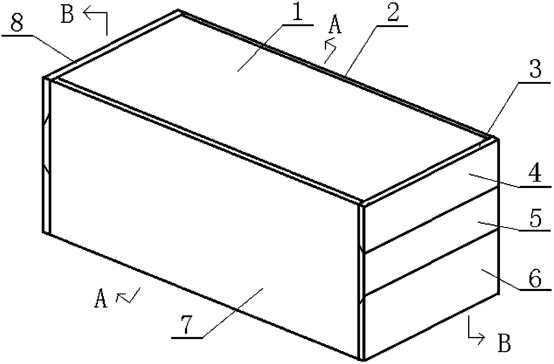
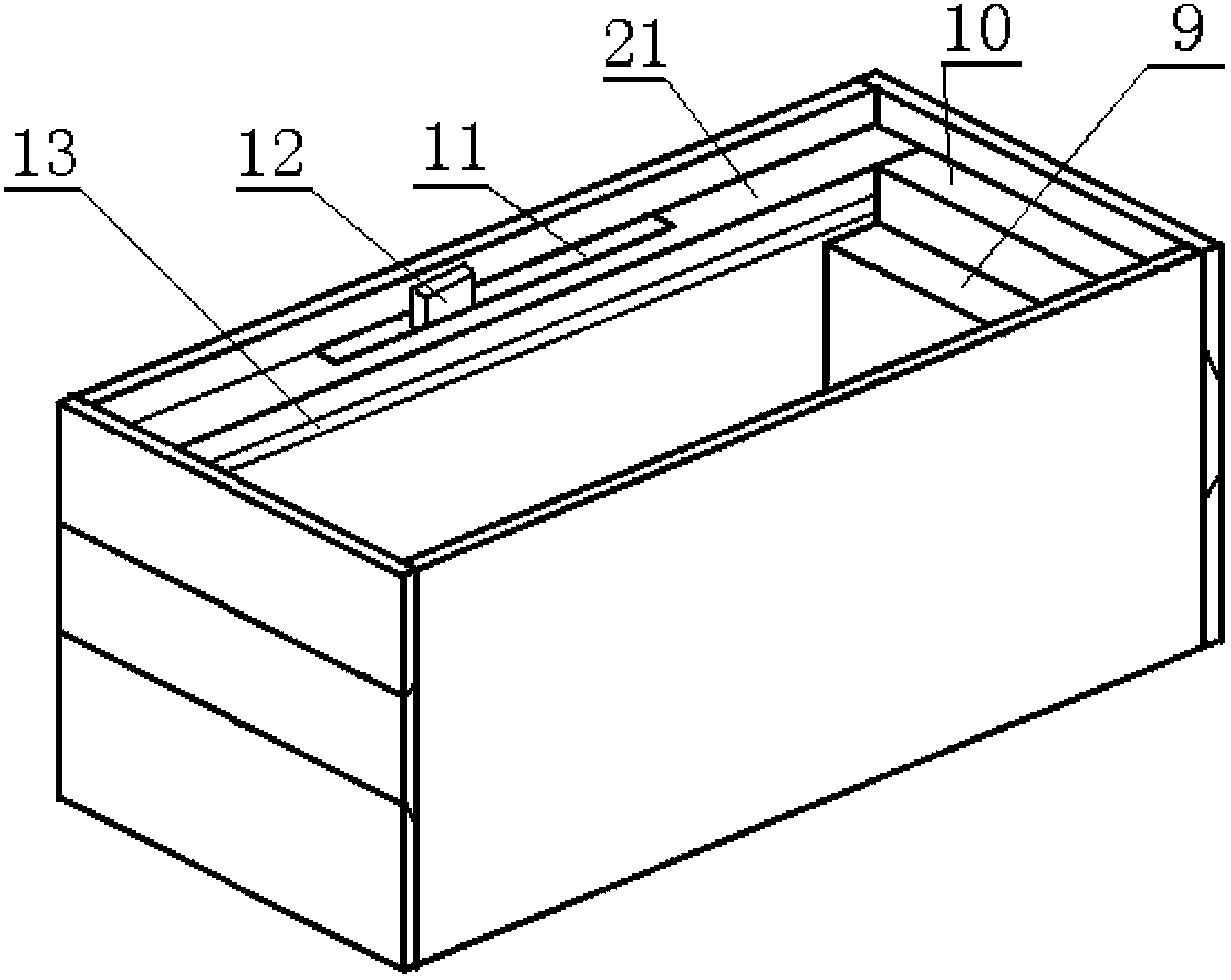
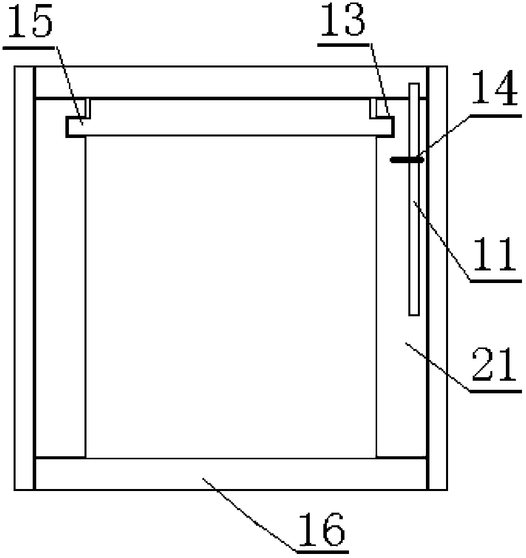
[0032] As shown in the drawings, a push-pull switch box includes an upper cover plate 1, a rear side plate 2, a right side plate 3, a front side plate 7, a left side plate 8 and a bottom plate 16; a rear side plate 2 and a front side plate 7 are composed of a panel and a fixed plate 21; the right side panel 3 adopts a push-pull mechanical lock structure, including a panel, a lock hole plate 10 and a lock slot plate 9; the panel of the right side panel 3 includes an upper clamping plate 4, a movable plate 5 And lower clamping plate 6, upper clamping plate 4 and lower clamping plate 6 are fixedly installed on the keyhole plate 10, and the contact surface of upper clamping plate 4, lower clamping plate 6 and movable plate 5 is an inclined surface, and movable plate 5 is provided with a lock block 17; The lock hole plate 10 of the right side plate 3 is provided with a lock hole 18, and the left and right edges are provided with convex strips 15; the lock groove plate 9 of the right...

Embodiment 2

[0034] As shown in the drawings, a push-pull switch box includes an upper cover plate 1, a rear side plate 2, a right side plate 3, a front side plate 7, a left side plate 8 and a bottom plate 16; a rear side plate 2 and a front side plate 7 are composed of a panel and a fixed plate 21; the right side panel 3 adopts a push-pull mechanical lock structure, including a panel, a lock hole plate 10 and a lock slot plate 9; the panel of the right side panel 3 includes an upper clamping plate 4, a movable plate 5 And lower clamping plate 6, upper clamping plate 4 and lower clamping plate 6 are fixedly installed on the keyhole plate 10, and the contact surface of upper clamping plate 4, lower clamping plate 6 and movable plate 5 is an inclined surface, and movable plate 5 is provided with a lock block 17; The lock hole plate 10 of the right side plate 3 is provided with a lock hole 18, and the left and right edges are provided with convex strips 15; the lock groove plate 9 of the right...

Embodiment 3

[0036] As shown in the drawings, a push-pull switch box includes an upper cover plate 1, a rear side plate 2, a right side plate 3, a front side plate 7, a left side plate 8 and a bottom plate 16; a rear side plate 2 and a front side plate 7 are all made up of panel and fixed plate 21; Right side plate 3 and left side plate 8 all have adopted push-pull type mechanical lock structure, comprise panel, keyhole plate 10 and lock groove plate 9; Said left side plate 8 and right side The panels of the plate 3 all include an upper clamping plate 4, a movable plate 5 and a lower clamping plate 6, and the upper clamping plate 4 and the lower clamping plate 6 are fixedly installed on the keyhole plate 10, and the contact surfaces of the upper clamping plate 4, the lower clamping plate 6 and the movable plate 5 are inclined. On the surface, the movable plate 5 is provided with a lock block 17; the keyhole plate 10 of the left side plate 8 and the right side plate 3 is provided with a lock h...


PUM


Abstract

The invention relates to a push-pull type opening and closing box. The box comprises an upper cover plate (1), a front side plate (7), a back side plate (2), a left side plate (8), a right side plate (3) and a bottom plate (16); and the box is characterized in that the right side plate (3) has a push-pull type mechanical lock structure and comprises a panel, a lock hole plate (10) and a lock groove plate (9); the panel comprises an upper splint (4), a movable plate (5) and a lower splint (6); the upper splint (4) and the lower splint (6) are fixedly mounted on the lock hole plate (10); a lock block (17) is arranged on the movable plate (5); a lock hole (18) is formed in the lock hole plate (10); a lock groove (19) is formed on the lock groove plate (9); and the lock groove (19) is step-shaped. The push-pull type opening and closing box provided by the invention has the advantages of novel conception, skillful design, skills needed during opening and capability of increasing opening interests.

Description

technical field [0001] The invention relates to a box provided with a switch or a lock, in particular to a box with an interesting push-pull switch which requires skill and is novel in conception. Background technique [0002] At present, manufacturers will use various means to increase profits in order to sell products, and packaging is one of the strategies. Manufacturers package products, which not only have the function of acting as a product protection god, but also have a positive promotional effect. With the market competition in recent years Intense, more people are trying their best to make it play the latter role. Good packaging should play the role of promotion, first of all, it must be able to attract consumers' attention, because only products that attract consumers' attention are likely to be purchased. Therefore, the packaging should use novel and unique shapes, bright and eye-catching colors, beautiful and exquisite patterns, and materials with their own cha...

Claims


Application Information

Patent Timeline
Patent Type & Authority Patents(China)
IPC IPC(8): B65D6/02B65D43/26
Inventor 周俊华
Owner 周俊华
Why Eureka
Try Eureka