
Socket and plug cooperated structure

A technology of matching structure and plug, applied in the direction of coupling device, base/housing, connecting device components, etc., can solve problems such as accidental power failure of electrical equipment, affecting the normal operation of electrical equipment, and plug detachment, etc., to avoid interference. Effect

Active Publication Date: 2018-06-15
NINGBO SDIAPER OPTOELECTRONICS
View PDF7 Cites 8 Cited by
  • Summary
  • Abstract
  • Description
  • Claims
  • Application Information

AI Technical Summary

Problems solved by technology

After the plug in the prior art is inserted into the socket, when the plug is subjected to a large external force, for example, when the plug is accidentally kicked, the plug is easily separated from the socket, which will cause accidental disconnection of the electrical equipment. The phenomenon of electricity, which will affect the normal operation of electrical equipment, and even lead to the phenomenon of data loss in the computer, and even cause damage to electrical appliances in severe cases

Method used


Image

  • Socket and plug cooperated structure
  • Socket and plug cooperated structure
  • Socket and plug cooperated structure

Examples


Embodiment Construction

[0014] The specific embodiments of the present invention will be further described in detail below in conjunction with the accompanying drawings.

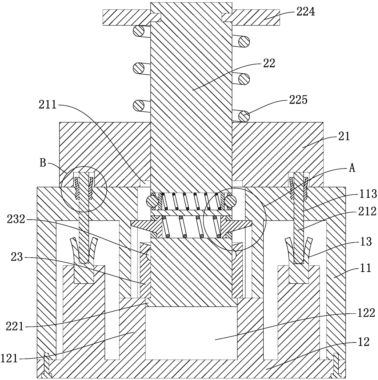
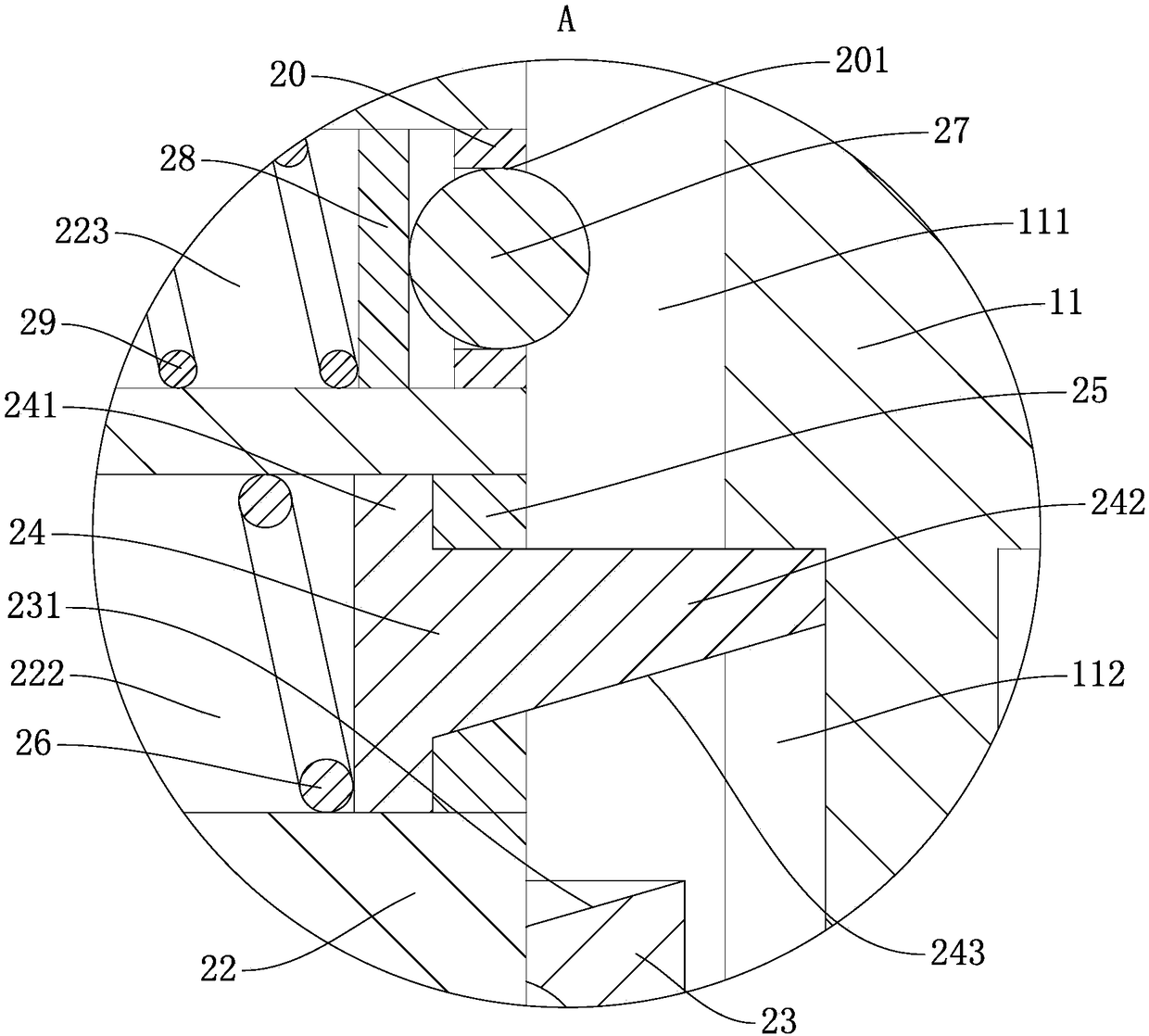
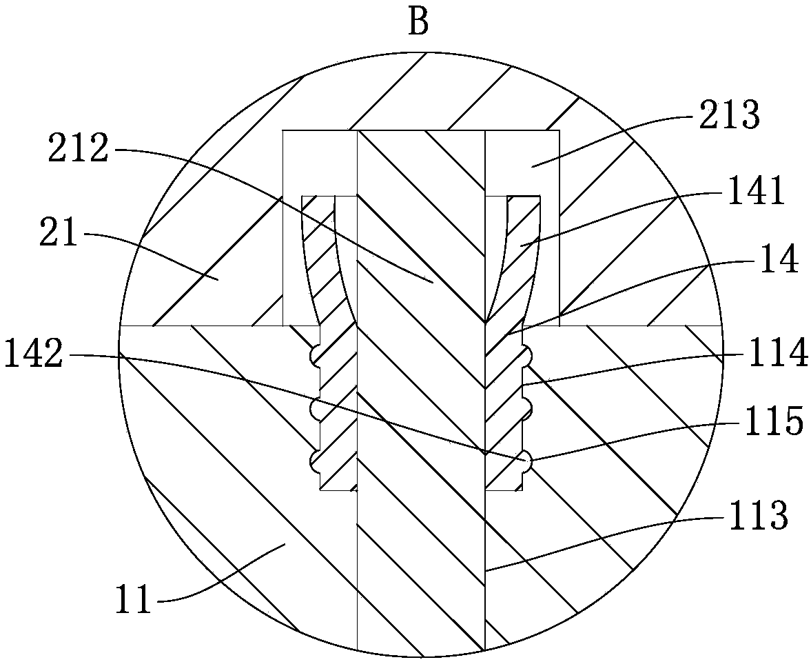
[0015] A mating structure of a socket and a plug, including a socket body and a plug body, the socket body includes a housing 11 and a base 12 fixed on the bottom of the housing 11, the plug body includes a shell 21, and the middle part of the shell 21 is vertically pierced with a plug Rod 22, the plug-in rod 22 is rotatably connected with the housing 21, the outside of the plug-in rod 22 bottom can slide up and down to cover the limit sleeve 23, and the outer wall of the plug-in rod 22 lower end is provided with a stopper 23 to prevent The limiting sleeve 23 breaks away from the annular flange 221 of the plug-in rod 22, the outer diameter of the annular flange 221 is smaller than the outer diameter of the restrictive sleeve 23, and the upper end surface of the base 12 below the plug-in rod 22 is provided with a The lower end surfa...


PUM


Abstract

The invention discloses a socket and plug cooperated structure. The socket body comprises a shell and a base. The plug body comprises a housing. A plugging rod is arranged in the middle part of the housing in a penetrating way. The external part of the lower part of the plugging rod is sleeved by a limiting sleeve. The external side wall of the lower end of the plugging rod is provided with an annular convex side. The upper end surface of the base arranged below the plugging rod is provided with a protrusion in which an inserting groove is arranged. First slide holes are transversely arrangedin the plugging rod in a penetrating way. Limiting blocks are connected in the first slide holes. Sealing caps are fixed on the end parts of the first slide holes. The middle part of the shell is provided with a channel. The internal side wall of the channel is provided with an annular chute. A first spring is embedded in the first slide hole arranged between a pair of the limiting blocks. Multiple circumferentially distributed push-pull handles are connected on the external side wall of the upper end of the plugging rod in a threaded way. The external part of the plugging rod arranged betweenthe push-pull handles and the housing is sleeved by third springs. The phenomenon that the plug body is separated from the socket body can be avoided so that accidental power outage of the electricalequipment can be avoided.

Description

technical field [0001] The invention belongs to the technical field of electric devices and relates to a matching structure of a socket and a plug. Background technique [0002] Sockets and plugs are electrical accessories commonly used in people's lives. When the plugs are inserted into the sockets, the electrical equipment is energized. After the plug in the prior art is inserted into the socket, when the plug is subjected to a large external force, for example, when the plug is accidentally kicked, the plug is easily separated from the socket, which will cause accidental disconnection of the electrical equipment. The phenomenon of electricity, which will affect the normal operation of electrical equipment, and even lead to the phenomenon of data loss in the computer, and even cause damage to electrical appliances in severe cases. Contents of the invention [0003] In order to solve the above problems, the present invention designs a locking structure of the socket and ...

Claims


Application Information

Patent Timeline
Patent Type & Authority Applications(China)
IPC IPC(8): H01R13/627H01R13/633H01R13/52H01R13/502
CPCH01R13/502H01R13/521H01R13/6278H01R13/633
Inventor 胡伟
Owner NINGBO SDIAPER OPTOELECTRONICS
Learn More