Refrigeration system, air conditioner and control method for air conditioner

A refrigeration system and control method technology, applied in refrigerators, refrigeration components, refrigeration and liquefaction, etc., can solve the problems of compressor oil shortage, refrigerant liquid liquid shock, affecting the service life of compressors, etc., and achieve extended service life, Improve the safety factor and solve the effect of liquid hammer

Active Publication Date: 2020-12-18
QINGDAO HISENSE HITACHI AIR CONDITIONING SYST
View PDF6 Cites 0 Cited by
  • Summary
  • Abstract
  • Description
  • Claims
  • Application Information

AI Technical Summary

Problems solved by technology

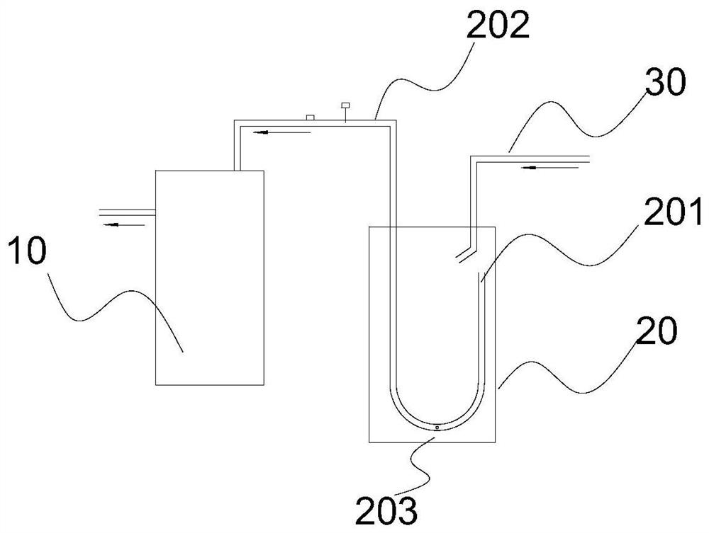
[0004] However, after the system runs for a long time, more and more oil droplets will gather at the bottom of the existing gas-liquid separator 20, and the lubricating oil cannot return to the compressor. The dry friction of the moving parts will generate a lot of heat, which will seriously affect the service life of the compressor. Therefore, the bottom of the U-shaped tube of the gas-liquid separator is always provided with an oil return hole 203. The purpose is to ensure that the lubricating oil can Continuously return to the compressor from the oil return hole
However, when the refrigeration system is shut down, there will be refrigerant liquid stored in the gas-liquid separator, and the oil return hole at the bottom of the U-shaped tube will be immersed in the refrigerant liquid, so there will be refrigerant liquid in the U-shaped tube. After the compressor starts up again, the refrigerant liquid will be sucked into the compressor causing a liquid hammer accident

Method used


Image

  • Refrigeration system, air conditioner and control method for air conditioner
  • Refrigeration system, air conditioner and control method for air conditioner
  • Refrigeration system, air conditioner and control method for air conditioner

Examples


Embodiment Construction

[0020] In the following, the present invention will be specifically described through exemplary embodiments. It should be understood, however, that elements, structures and characteristics of one embodiment may be beneficially incorporated in other embodiments without further recitation.

[0021] In describing the present invention, it is to be understood that the terms "center", "upper", "lower", "front", "rear", "left", "right", "vertical", "horizontal", The orientations or positional relationships indicated by "top", "bottom", "inner", "outer", etc. are based on the orientations or positional relationships shown in the drawings, and are only for the convenience of describing the present invention and simplifying the description, rather than indicating or implying References to devices or elements must have a particular orientation, be constructed, and operate in a particular orientation and therefore should not be construed as limiting the invention.

[0022] The terms "fi...


PUM


Abstract

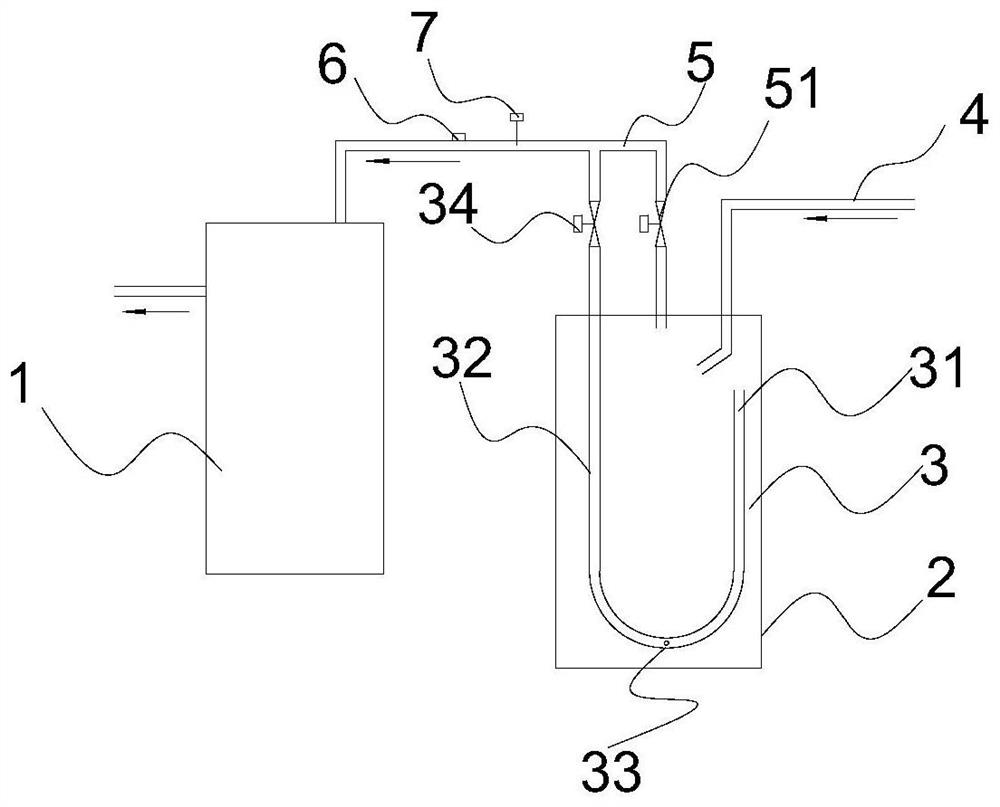
The invention provides a refrigerating system, an air conditioner and a control method of the air conditioner. The refrigerating system comprises a compressor and an air-liquid separator. The air-liquid separator is provided with an air feeding pipe and air discharging pipes, the air feeding end of the first air discharging pipe is arranged inside the air-liquid separator, and the air dischargingend of the first air discharging pipe is connected to an air return opening of the compressor. The air feeding end of the second air discharging pipe stretches into the air-liquid separator and is arranged at the top of the air-liquid separator, and the air discharging end of the second air discharging pipe is connected to the air returning opening of the compressor. The first air discharging pipeis provided with a first control valve, and the second air discharging pipe is provided with a second control valve. The air conditioner and the control method of the air conditioner are both based on the refrigerating system. By means of the refrigerating system, the air conditioner and the control method of the air conditioner, the liquid impact problem in the start process of the compressor, the liquid impact problem in the steady operation process and the oil return problem in the operation process are effectively solved, the function of adjusting the air sucking superheat degree of the compressor is achieved, therefore, the safety coefficient of the compressor is improved, and the service life of the compressor is prolonged.

Description

technical field [0001] The invention belongs to the refrigeration field, in particular to a refrigeration system of an air conditioner. Background technique [0002] At present, one of the four major components of the refrigeration system is the compressor. The compressor is also called the heart of the refrigeration system. The reliability of the compressor is directly related to the reliability of the entire system. The service life of the system is directly related, and the two major killers of compressor damage are poor oil return and liquid hammer. [0003] Aiming at the liquid hammer problem, the prior art solves the problem by installing a gas-liquid separator at the air inlet of the compressor. Such as figure 1 As shown, a gas-liquid separator 20 is installed before the suction port of the compressor 10, and the outside of the gas-liquid separator 20 is a cylindrical tank with two pipes (an inlet pipe 30, A gas outlet pipe), from the internal cross-sectional view ...

Claims


Application Information

Patent Timeline
Patent Type & Authority Patents(China)
IPC IPC(8): F25B43/02F25B49/02
CPCF25B43/02F25B49/022F25B2400/077F25B2500/28
Inventor 孙福涛孙龙潘翠连周洋
Owner QINGDAO HISENSE HITACHI AIR CONDITIONING SYST
Why Eureka
Try Eureka