
Scroll type refrigeration compressor

A refrigeration compressor and scroll technology, which is applied in the field of scroll compressors, can solve the problems of damage to the scroll, reduction of the viscosity of the lubricating oil, and large load.

Active Publication Date: 2021-09-14
广东睿德新能源科技有限公司
View PDF5 Cites 0 Cited by
  • Summary
  • Abstract
  • Description
  • Claims
  • Application Information

AI Technical Summary

Problems solved by technology

[0003] Scroll compressors are generally used in central air conditioners or large refrigerators. After the traditional compressor is finished, a small amount of high-pressure refrigerant will flow back into the compressor when the compressor is turned off. The refrigerant will interact with the lubrication inside the compressor. Oil combination, after a long time of work, when the compressor is started, a large number of air bubbles will appear in the lubricating oil inside the compressor, which is likely to cause liquid hammer phenomenon, resulting in a large load of the compressor when it is working, and easily causing damage to the scroll in the compressor , reduce the service life of the compressor, and at the same time cause the compressor to make a lot of noise when it is working; in addition, when the compressor is turned off, the refrigerant that is not discharged from the high-pressure chamber of the compressor will move into the low-pressure chamber, and finally from the intake air However, there is still a small amount of refrigerant that has not been completely exhausted. The refrigerant is mixed with the lubricating oil, and the viscosity of the lubricating oil decreases, causing rapid wear of the moving parts inside the compressor, causing damage to the moving parts inside the compressor, and reducing the compressor's performance. service life

Method used


Image

  • Scroll type refrigeration compressor
  • Scroll type refrigeration compressor
  • Scroll type refrigeration compressor

Examples


Embodiment Construction

[0035] The following will clearly and completely describe the technical solutions in the embodiments of the present invention with reference to the accompanying drawings in the embodiments of the present invention. Obviously, the described embodiments are only some, not all, embodiments of the present invention. Based on the embodiments of the present invention, all other embodiments obtained by persons of ordinary skill in the art without making creative efforts belong to the protection scope of the present invention.

[0036] In describing the present invention, it is to be understood that the terms "center", "longitudinal", "transverse", "length", "width", "thickness", "upper", "lower", "front", " Back", "Left", "Right", "Straight", "Horizontal", "Top", "Bottom", "Inner", "Outer", "Clockwise", "Counterclockwise", etc. or The positional relationship is based on the orientation or positional relationship shown in the drawings, which is only for the convenience of describing t...


PUM


Abstract

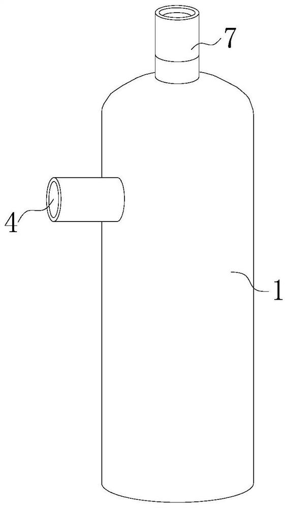
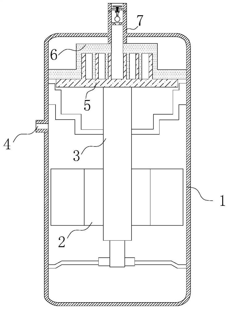
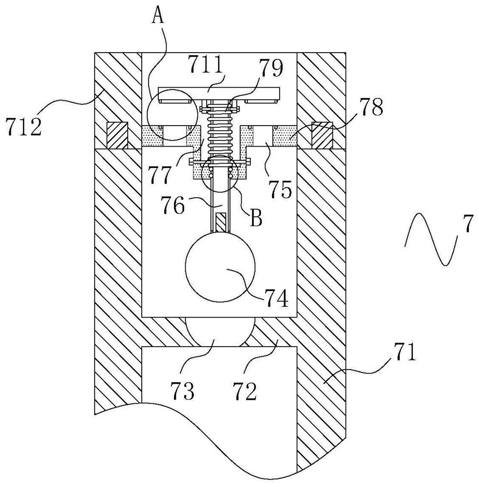
The invention relates to the technical field of scroll compressors, in particular to a scroll type refrigeration compressor which comprises a shell. An air inlet is fixedly formed in the position, close to the center, of one side of the outer surface of the shell; a rotor is fixedly installed at the center of the inner surface of the shell; a rotating shaft is fixedly installed at the center of the rotor; a movable vortex plate is fixedly installed at the top end of the rotating shaft; a static vortex plate is arranged on the upper surface of the movable vortex plate; and a flow stopping mechanism is fixedly installed in the center of the upper surface of the shell. According to the scroll type refrigeration compressor provided by the invention, when the compressor stops working, a high-pressure refrigerant is not generated any more, a flow stopping bead is not jacked up any more, a spring can drive a cover disc, a connecting rod and the flow stopping bead to move downwards due to contraction force, finally, the flow stopping bead can enter an arc-shaped hole, and tight closing is formed, so that the refrigerant is effectively prevented from flowing back into the compressor when the compressor is closed, the problem of liquid impact caused by combination of cooling liquid and lubricating oil in the compressor is avoided, and meanwhile, the problem of noise caused by the compressor is avoided.

Description

technical field [0001] The invention relates to the technical field of scroll compressors, in particular to a scroll refrigeration compressor. Background technique [0002] A scroll compressor is a volumetric compression compressor. The compression components are composed of an orbiting scroll and a fixed scroll, including many structures that make the gas passing through the compressor casing flow in separate ways to reduce entrained oil. The characteristic, the scroll compressor, is more than 30% higher in volumetric efficiency than the traditional piston machine, and has low noise. [0003] Scroll compressors are generally used in central air conditioners or large refrigerators. After the traditional compressor is finished, a small amount of high-pressure refrigerant will flow back into the compressor when the compressor is turned off. The refrigerant will interact with the lubrication inside the compressor. Oil combination, after a long time of work, when the compressor...

Claims


Application Information

Patent Timeline
Patent Type & Authority Applications(China)
IPC IPC(8): F04C18/02F04C29/02F04C29/04F04C29/00F04C29/06
CPCF04C18/0223F04C29/02F04C29/04F04C29/00F04C29/06
Inventor 张海涛夏欢
Owner 广东睿德新能源科技有限公司
Learn More