Fan control system

A fan control and fan technology, applied in pump control, electric temperature control, non-variable-capacity pumps, etc., can solve problems such as high temperature and damage to working components, reduce huge deviations, stabilize fan speed, solve The effect of high noise and high power consumption

Inactive Publication Date: 2008-07-30
CHROMA ELECTRONICS SHENZHEN
View PDF0 Cites 21 Cited by
  • Summary
  • Abstract
  • Description
  • Claims
  • Application Information

AI Technical Summary

Problems solved by technology

In this way, it will be very likely to cause the temperature of the working components to be higher

Method used


Image

  • Fan control system
  • Fan control system
  • Fan control system

Examples


Embodiment Construction

[0061] The specific embodiments adopted by the present invention will be further described through the following embodiments and attached drawings.

[0062] Since the fan control system provided by the present invention can be widely used in various systems with cooling or heat dissipation fans, and its combination implementations are too numerous to enumerate, so it is not repeated here, and only two preferred implementations are listed. example to illustrate.

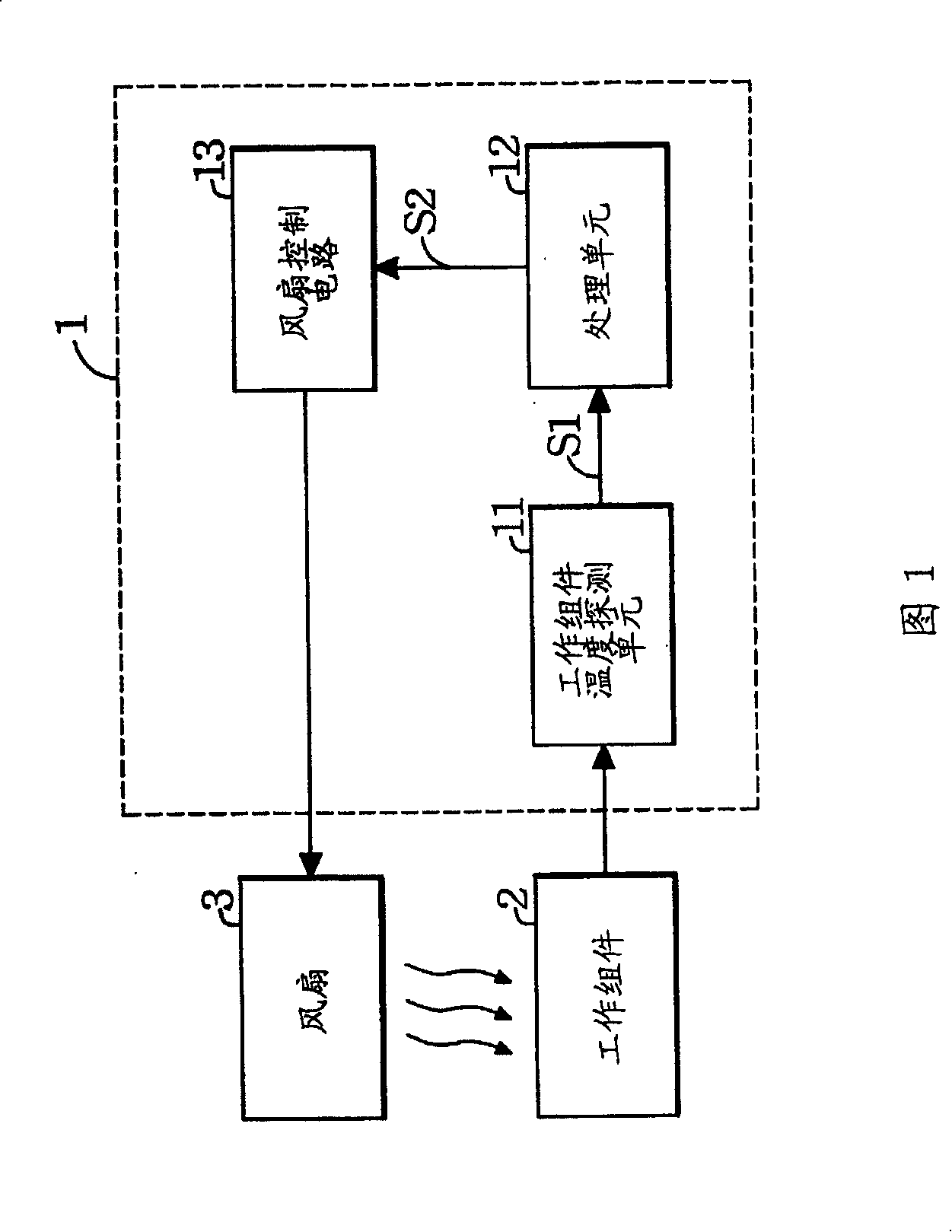
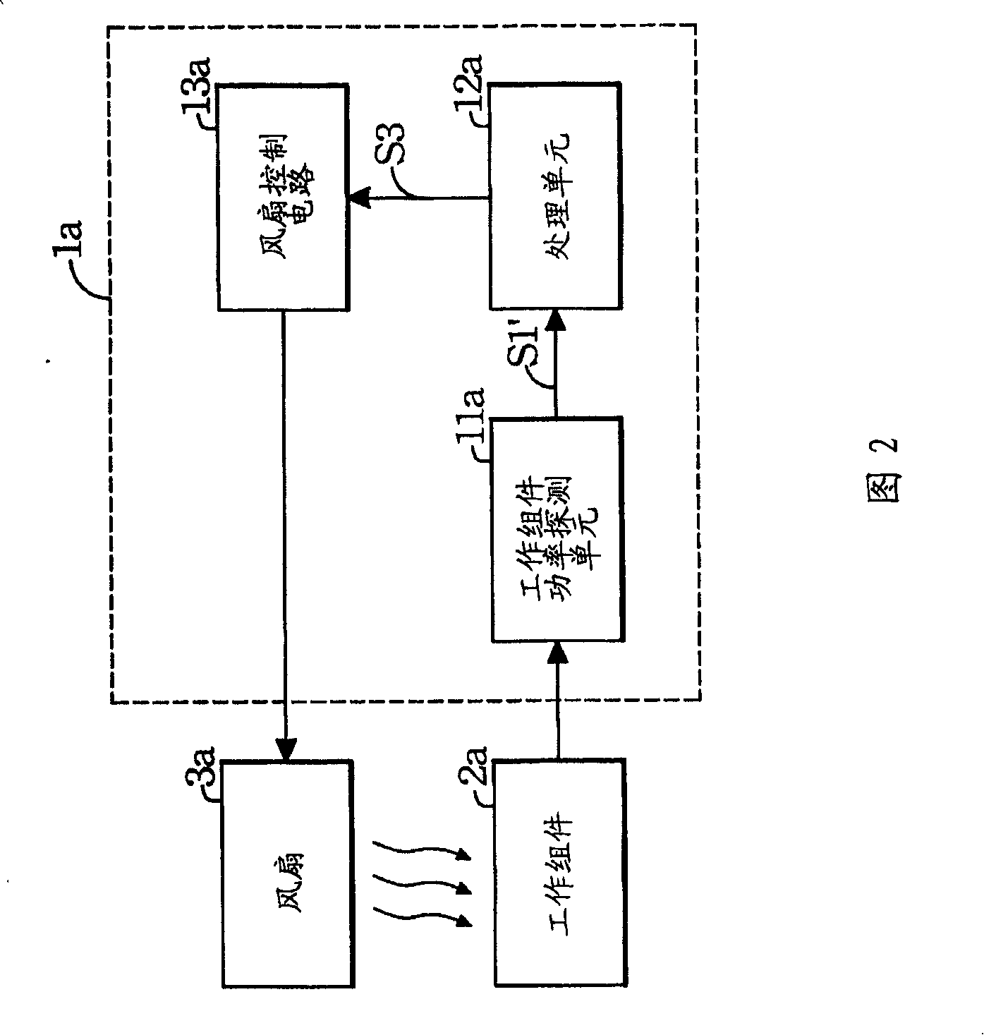
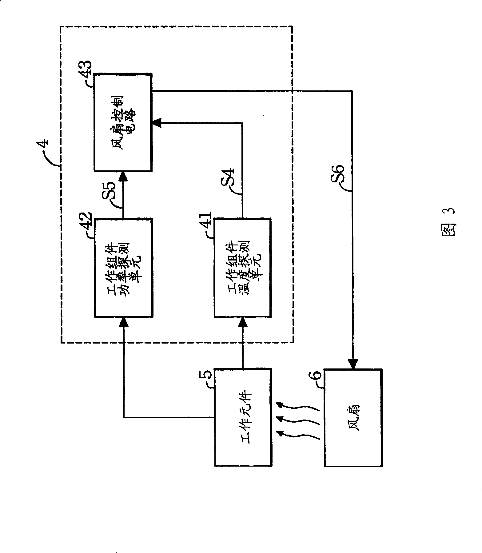
[0063] Please refer to FIG. 3 , which is a functional block diagram showing the first embodiment of the present invention. As shown in the figure, a fan control system 4 is used to detect the temperature and power of a working component 5 , so as to control the speed of a fan 6 used to cool the working component 5 . The fan control system 4 includes a working component temperature detection unit 41 , a working component power detection unit 42 and a fan control circuit 43 . Wherein, the working component temperature...


PUM


Abstract

The invention relates to a fan control system, which is used for detecting temperature and power of at least a work component to control the rotating speed of at least a fan used for cooling the work component. The fan control system comprises at least a work component temperature detecting unit and a work component power detecting unit to detect the temperature and the power of the work component to respectively obtain the temperature of the work component and the power of the work component. The fan control system also comprises a fan control circuit, and the fan control circuit resets lower limit reference temperature, upper limit reference temperature and reference power in advance, wherein, the upper limit reference temperature is higher than the lower limit reference temperature. After being compared with the temperature of the work component and the power of the work component, the invention outputs a control signal to control the rotating speed of the fan. When the fan control system of the invention is adopted, the effects of stabilizing rotate speed of the fan and reducing instant activation noise and protecting the work component can be received.

Description

technical field [0001] The invention relates to a fan control system, in particular to a fan control system which detects the temperature and power of working components and controls the fan speed. Background technique [0002] In general electronic devices or production systems, it is often necessary to effectively control the temperature of the device, system or environment in order to ensure that the device or system operates in a high-efficiency environment. In order to effectively control the operating temperature of these electronic devices (such as computers) or production systems (such as air-cooled quenching processing systems), in addition to heating and constant temperature feedback systems, cooling systems also play a very important role. In these cooling systems, most of the cooling methods used are nothing more than air-cooled, liquid-cooled or solid-state heat conduction. Among them, because the operating cost of the air-cooled type is generally relatively lo...

Claims


Application Information

Patent Timeline
IPC IPC(8): F04D27/00G05D23/19
Inventor 郭贝仓蒋兴文陈宏泰
Owner CHROMA ELECTRONICS SHENZHEN
Why Eureka
Try Eureka