Expansion deformation connecting device and processing method thereof

A technology for connecting devices and connecting components, which is applied to bridge parts, bridge materials, bridges, etc., can solve problems such as subsidence, achieve uniform bearing capacity, and avoid the effect of being compressed and uplifted

Active Publication Date: 2018-06-29
CHINA MCC5 GROUP CORP
View PDF6 Cites 1 Cited by
  • Summary
  • Abstract
  • Description
  • Claims
  • Application Information

AI Technical Summary

Problems solved by technology

[0003] Aiming at the above-mentioned technical problems, the present invention provides a telescopically deformable connecting device, which effectively solves the problem of uniform telescopic deformation between connected objects, and also has a certain uniform bearing capacity, which greatly avoids the problems caused by traditional caulking methods. The gap filler is compressed and bulged, or stretched and collapsed

Method used


Image

  • Expansion deformation connecting device and processing method thereof
  • Expansion deformation connecting device and processing method thereof
  • Expansion deformation connecting device and processing method thereof

Examples


Embodiment 1

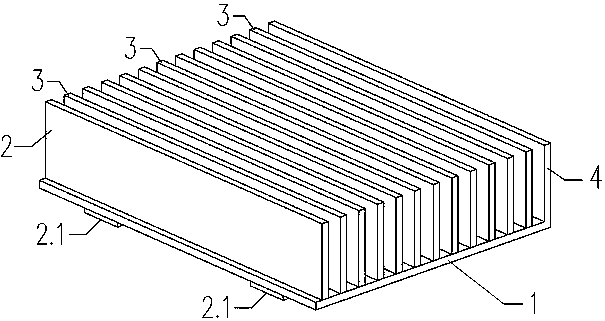
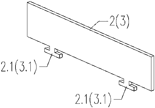
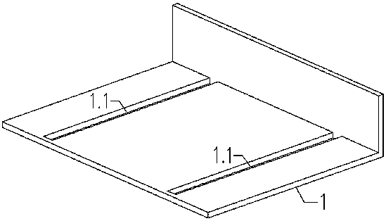
[0033] The telescopic and deformable connection device includes a horizontal support plate 1, a plurality of vertical support plates, the vertical support plates are vertically arranged on the horizontal support plate 1, and the vertical support plates include corresponding fixed end vertical supports located at both ends. The support plate 4, the movable end vertical support plate 2 and the movable middle vertical support plate 3 in the middle; the horizontal support plate 1 is longitudinally provided with two or more parallel horizontal support plate chute 1.1, The bottoms of the movable end vertical support plate 2 and the movable middle vertical support plate 3 are provided with corresponding convex structure 2.1 and convex structure 3.1 corresponding to the horizontal support plate chute, and are clamped on the horizontal support plate slide. In the groove 1.1, an elastic filler is arranged between two adjacent vertical support plates.

[0034] Preferably, one end of the ...

Embodiment 2

[0041] The telescopic and deformable connection device includes a horizontal support plate 1, a plurality of vertical support plates, the vertical support plates are vertically arranged on the horizontal support plate 1, and the vertical support plates include corresponding fixed end vertical supports located at both ends. The support plate 4, the movable end vertical support plate 2 and the movable middle vertical support plate 3 in the middle; the horizontal support plate 1 is longitudinally provided with two or more parallel horizontal support plate chute 1.1, The bottoms of the movable end vertical support plate 2 and the movable middle vertical support plate 3 are provided with corresponding convex structures 2.1 and 3.1 corresponding to the horizontal support plate chute, and snapped into the horizontal support plate chute 1.1 ; An elastic filler is arranged between two adjacent vertical support plates.

[0042] Preferably, the horizontal support plate (1) and the fixed ...

Embodiment 3

[0051] The telescopic and deformable connection device includes a horizontal support plate 1, a plurality of vertical support plates, the vertical support plates are vertically arranged on the horizontal support plate 1, and the vertical support plates include corresponding fixed end vertical supports located at both ends. The support plate 4, the movable end vertical support plate 2 and the movable middle vertical support plate 3 in the middle; the fixed end vertical support plate 4 is bent 90° by one end of the horizontal support plate 1 made. That is to say, after the horizontal support plate 1 is bent by 90°, the end that is equal in height to the movable end vertical support plate 2 or the movable middle vertical support plate 3 becomes a deformed fixed end vertical support plate 4, the remaining other end has just become a new horizontal support plate 1, and its effect is exactly the same as the horizontal support plate 1 in the foregoing embodiment.

[0052] Preferably...


PUM


Abstract

The invention discloses an expansion deformation connecting device and a processing method thereof. The device comprises a horizontal supporting piece and multiple vertical supporting pieces perpendicularly arranged on the horizontal supporting piece. The vertical supporting pieces comprise the movable end vertical supporting piece, the fixed end vertical supporting piece and the movable middle vertical supporting pieces, wherein the movable end vertical supporting piece and the fixed end vertical supporting piece are located at the two ends of the horizontal supporting piece separately, and the movable middle vertical supporting pieces are located in the middle; and the movable end vertical supporting piece and the movable middle vertical supporting pieces can transversely slide on the horizontal supporting piece, the fixed end vertical supporting piece and the horizontal supporting piece are fixedly connected at the end, and elastic stuffing is arranged between every two adjacent vertical supporting pieces. The purpose of even expansion deformation between connected objects is effectively achieved, meanwhile, certain vertical even bearing capacity is achieved, and the problem that gap stuffing is compressed to bulge or stretched to collapse in a traditional gap filling method is solved.

Description

technical field [0001] The invention belongs to the technical field of transportation and construction engineering, and in particular relates to a telescopically deformable connecting device and a processing method for connecting two objects and filling gaps between them. Background technique [0002] In technical fields such as bridges and construction engineering, there will be connection problems of various components, and expansion joints will be left in order to cope with the thermal expansion and cold contraction of materials. As for how to fill expansion joints, relevant technical personnel have been constantly exploring and working hard to solve the problem. Especially for the connection between building materials with relatively large expansion coefficients and the caulking of expansion joints, it is not only required to effectively solve the problem of expansion and deformation between connected objects, but also to have a certain uniform bearing capacity to avoid ...

Claims


Application Information

Patent Timeline
Patent Type & Authority Applications(China)
IPC IPC(8): E01D19/06E04B1/68E01D101/30
CPCE01D19/06E01D19/065E04B1/68E04B1/6801E01D2101/30
Inventor 周元王义王永景唐丽廖兴国姜友荣黄珊李丽
Owner CHINA MCC5 GROUP CORP
Why Eureka
Try Eureka