VR camera capable of rotating in all directions

A camera, all-round technology, used in supporting machines, image communication, mechanical equipment, etc., can solve the problems of inability to automatically adjust the height, inconvenient operation, difficult rotation, etc., to achieve the effect of convenient positioning, fast lifting and simple operation

Inactive Publication Date: 2018-06-29
诺传百世(成都)教育科技有限公司
View PDF0 Cites 10 Cited by
  • Summary
  • Abstract
  • Description
  • Claims
  • Application Information

AI Technical Summary

Problems solved by technology

[0002] At present, with the technological development of photographic equipment in modern society, high-definition photographic equipment has been popularized to the vast number of amateur photographers. During general walking and mobile photography, the anti-shake function of modern photographic equipment can meet the photography needs of users. Now Nowadays, VR cameras are getting more and more people's love, but due to the design reasons of traditional VR cameras, when rotating the VR camera, the VR camera needs to be connected to the mounting frame to rotate together, and at the same time, the height cannot be automatically adjusted, which is inconvenient to operate and difficult to rotate. Therefore need to improve

Method used


Image

  • VR camera capable of rotating in all directions
  • VR camera capable of rotating in all directions

Examples


Embodiment Construction

[0016] The present invention will be further described below in conjunction with the accompanying drawings, but the protection scope of the present invention is not limited to the following description.

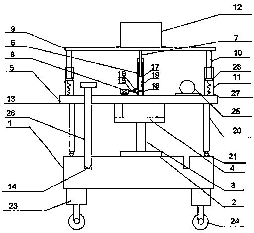
[0017] Such as figure 1 As shown, a VR camera that can rotate in all directions includes a base plate 1, a rotating motor 2 is arranged in the middle of the upper end surface of the base plate 1, and a cylinder 3 is connected to the rotating motor 2, and the cylinder 3 The upper end is provided with a bearing 4, the upper end of the cylinder 3 is fixedly welded to the lower end of the inner ring of the bearing 4, the upper end of the outer ring of the bearing 4 is welded with a turntable 5 through a connecting rod, and the middle part of the upper end surface of the turntable 5 is provided with a main Rod 6, a pole 7 is provided on the upper side of the main pole, and a rotating lifting device is arranged between the main pole 6 and the supporting pole 7, and the rotating lif...


PUM


Abstract

The invention discloses a VR camera capable of rotating in all directions. The VR camera comprises a bottom plate, wherein a rotating motor is arranged in the middle part of the upper end surface of the bottom plate, a column body is connected to the rotating motor, a bearing is arranged at the upper end of the column body, and the upper end of the column body is fixedly welded to the lower end ofan inner ring of the bearing; a rotating disc is welded to the upper end of the outer ring of the bearing through connecting rods, a main rod is arranged in the middle part of the upper end surface of the rotating disc, a supporting rod is arranged on the upper side of the main rod, and a rotating lifting device is arranged between the main rod and the supporting rod; the rotating lifting devicecomprises a driving motor and a lifting vertical column, wherein the lower end of the lifting vertical column is arranged at the bottom part of the main rod, the upper end of the lifting vertical column is fixedly connected to the supporting rod, and the lifting vertical column is electrically connected to the driving motor; the upper part of the supporting rod is connected to a horizontally-arranged lifting plate, guide rods are arranged at the four corners of the lifting plate, guide columns are arranged at the position, corresponding to the guide rods, of the rotary disc, and the guide rodsare arranged in the guide columns; and the upper end surface of the lifting plate is provided with a VR camera body through screws; and a first inserting hole is formed in the rotating disc, a secondinserting hole is formed in the bottom plate, and the lower end of the inserting rod penetrates through the first inserting hole to be inserted into the interior of the second inserting hole. The VRcamera has the advantages that operation is simple and convenient, rotating and lifting are rapid, positioning is convenient, and the VR camera is suitable for large-scale popularization.

Description

technical field [0001] The invention relates to the technical field of VR cameras, in particular to a VR camera capable of omnidirectional rotation. Background technique [0002] At present, with the technological development of photographic equipment in modern society, high-definition photographic equipment has been popularized to the vast number of amateur photographers. During general walking and mobile photography, the anti-shake function of modern photographic equipment can meet the photography needs of users. Now Nowadays, VR cameras are getting more and more people's love, but due to the design reasons of traditional VR cameras, when rotating the VR camera, the VR camera needs to be connected to the mounting frame to rotate together, and at the same time, the height cannot be automatically adjusted, which is inconvenient to operate and difficult to rotate. Hence the need for improvement. Contents of the invention [0003] The purpose of the present invention is to ...

Claims


Application Information

Patent Timeline
Patent Type & Authority Applications(China)
IPC IPC(8): F16M11/24F16M11/08H04N5/225
CPCF16M11/08F16M11/24H04N23/50
Inventor 林煜卢德烜黄庆维刘凌韵
Owner 诺传百世(成都)教育科技有限公司
Why Eureka
Try Eureka