Smokeless boiler
A boiler and soot technology is applied in the field of smokeless boilers to achieve the effect of solving the problem of environmental pollution and solving the waste of resources
- Summary
- Abstract
- Description
- Claims
- Application Information
AI Technical Summary
Problems solved by technology
Method used
Image

Examples
Embodiment approach 1
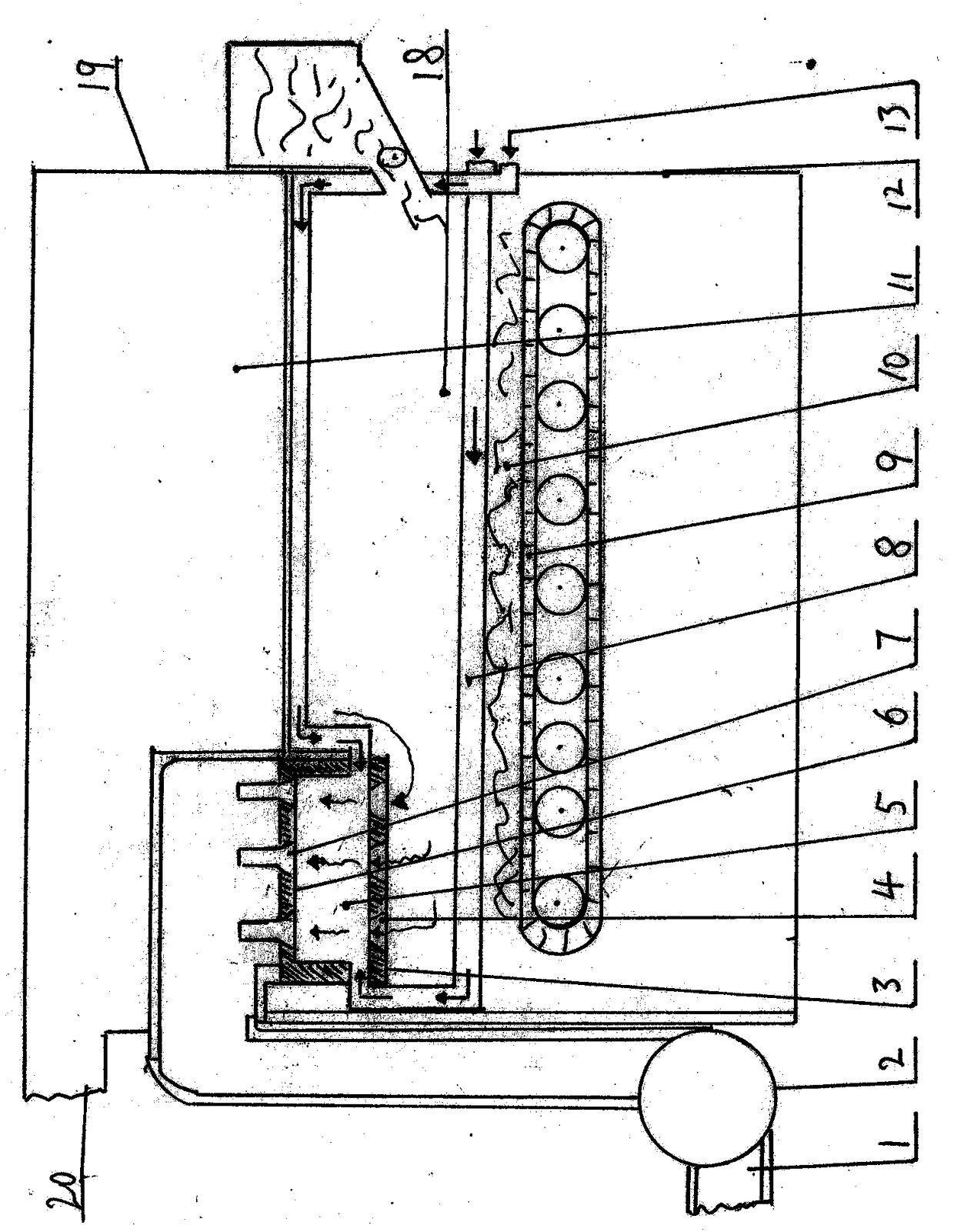
[0055] A smokeless boiler, comprising: a thermal cycle furnace body 19, a combustion furnace 18, and a high-temperature combustion chamber 5; the thermal cycle furnace body 19 is provided with an outer shell and an inner shell 11, and the outer shell is provided with a return pipe (not shown) and an outlet Water pipe 20, inner shell 11, fire grate 9, fuel 10, smoke exhaust pipe 1, smoke exhaust fan 2,
[0056] It is characterized in that: the smokeless boiler is creatively changed from a traditional smoke outlet to a semi-closed high-temperature combustion chamber 5 at the smoke outlet of the furnace;
[0057] The high-temperature combustion-supporting chamber 5 of the smokeless boiler is provided with a lower end cover 3 and an upper end cover 6;
[0058] The lower end cover 3 of the high-temperature combustion-supporting chamber 5 of the smokeless boiler is provided with a furnace hole 4,
[0059] The upper end cover 6 of the high-temperature combustion-supporting chamber 5 o...
Embodiment approach 2
[0069] A smokeless boiler includes: a thermal cycle furnace body 19, a combustion furnace 18, and a high-temperature combustion chamber 5; the thermal cycle furnace body 19 is provided with an outer shell and an inner shell 11, and the outer shell is provided with a return pipe (not shown) and an outlet pipe 20, inner shell 11, fire grate 9, fuel 10, exhaust pipe 1, exhaust fan 2,
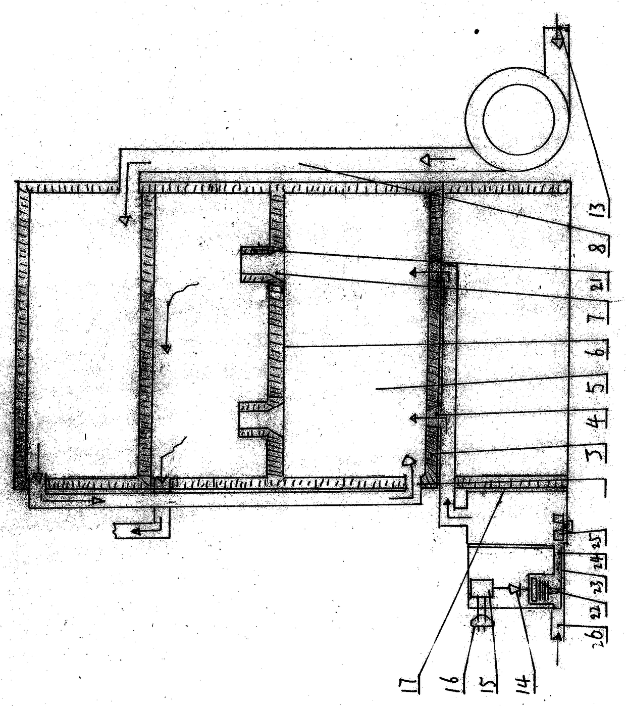
[0070] It is characterized in that: the furnace gas combustion device of the energy-saving furnace is creatively changed from the traditional furnace mouth to a semi-closed high-temperature combustion-supporting chamber 5 at the smoke upward exit of the furnace; the high-temperature combustion-supporting chamber 5 of the smokeless boiler is set as Porous grid-shaped; the grid-shaped high-temperature combustion-supporting chamber 5 of the smokeless boiler is provided with an air passage 8 communicating with the outside of the combustion furnace 18, and the air passage 8 can be heated by the combustio...
Embodiment approach 3
[0078] A smokeless boiler, comprising: a combustion furnace 18, a high-temperature combustion chamber 5,
[0079] It is characterized in that: the soot after fuel combustion in the furnace of the smokeless boiler is discharged through the smoke exhaust port of the furnace and enters the high-temperature combustion chamber 5;
[0080] The bottom of the high-temperature combustion-supporting chamber 5 of the smokeless boiler is provided with a soot passage communicating with the upper part and passing through the upper part of the high-temperature combustion-supporting chamber 5, and the high-temperature soot after combustion in the combustion furnace 18 can enter the high-temperature combustion-supporting chamber 5 through the soot passage; A smoke pipe is arranged on the smoke channel of the high temperature combustion chamber 5 of the smokeless boiler;
[0081] The high-temperature combustion-supporting chamber 5 of the smokeless boiler is provided with an air channel 8 commu...
PUM
 Abstract
Description
Claims
Application Information
 - R&D Engineer
- R&D Manager
- IP Professional
- Industry Leading Data Capabilities
- Powerful AI technology
- Patent DNA Extraction
Browse by: Latest US Patents, China's latest patents, Technical Efficacy Thesaurus, Application Domain, Technology Topic.
© 2024 PatSnap. All rights reserved.Legal|Privacy policy|Modern Slavery Act Transparency Statement|Sitemap