Embedding component in component carrier by component fixation structure

A fixed structure and component bearing technology, applied in printed circuit components, semiconductor/solid-state device components, electrical components, etc., can solve problems such as difficulties

Active Publication Date: 2018-06-29
AT & S AUSTRIA TECH & SYSTTECHN AKTIENGES
View PDF4 Cites 1 Cited by
  • Summary
  • Abstract
  • Description
  • Claims
  • Application Information

AI Technical Summary

Problems solved by technology

[0003] Also, efficiently embedding the part into the part carrier is pr

Method used


Image

  • Embedding component in component carrier by component fixation structure
  • Embedding component in component carrier by component fixation structure
  • Embedding component in component carrier by component fixation structure

Examples


Embodiment Construction

[0069] Before the exemplary embodiments will be described in further detail with reference to the accompanying drawings, some basic considerations on which the exemplary embodiments of the present invention are developed will be outlined.

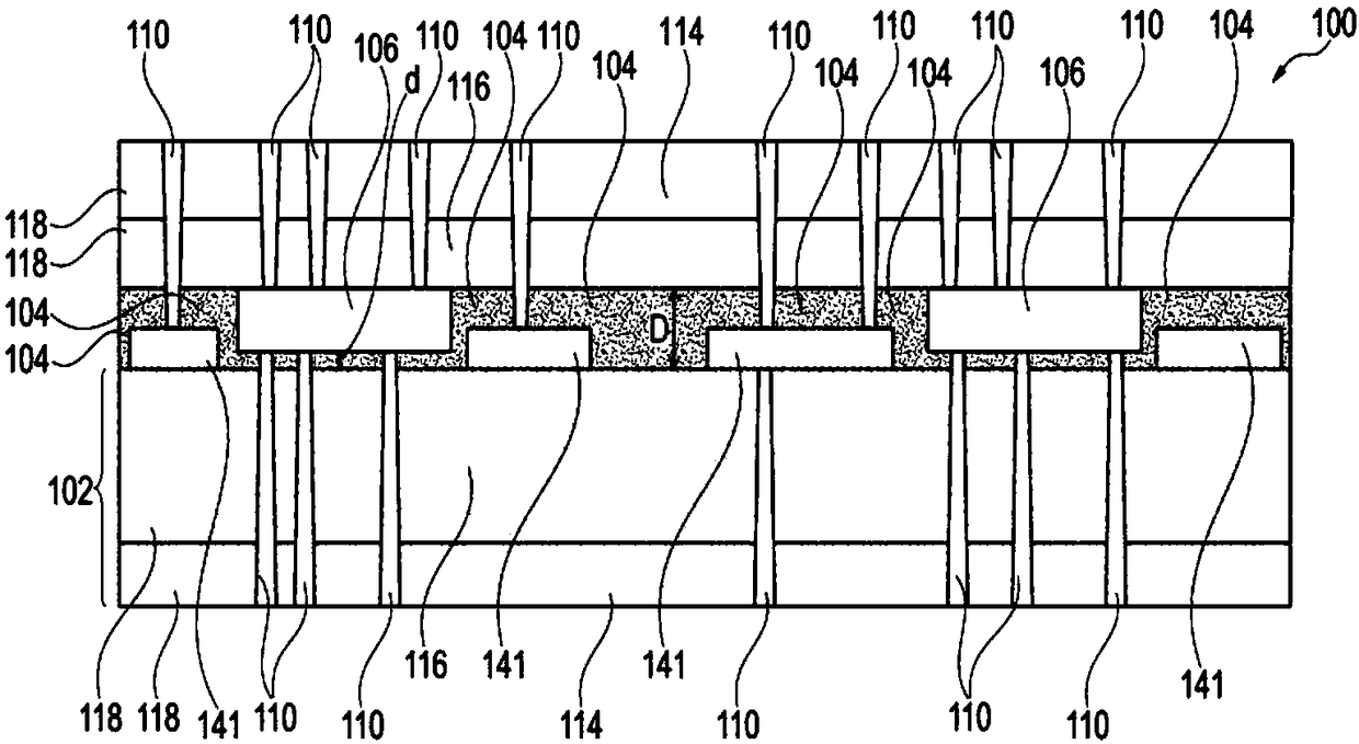
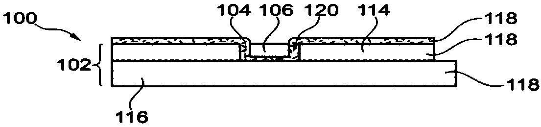
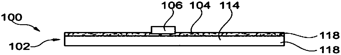
[0070] According to an exemplary embodiment of the present invention, a method of embedding a component exhibiting warpage is provided. However, this method can also be performed on components that do not exhibit warpage.

[0071]Components exhibiting warpage are a significant problem when they are to be embedded in a component carrier such as a printed circuit board (PCB). In particular, this can cause problems when picking and placing parts with warpage. Traditionally, there has been no reasonable opportunity to integrate components with warpage into PCBs. The reason for this is that embedding a component with warpage in a component carrier such as a PCB generally translates as a whole into a warpage of the component carrier. This may ...


PUM

PropertyMeasurementUnit
Thicknessaaaaaaaaaa
Thicknessaaaaaaaaaa

Abstract

A method of manufacturing a component carrier, wherein the method comprises covering a main surface of a base structure at least partially by a component fixation structure, mounting a component on acarrier, and interconnecting the base structure with the carrier so that the component extends partially into the component fixation structure.

Description

technical field [0001] The invention relates to a method for producing a component carrier, a semi-finished product and a component carrier. Background technique [0002] In the case of increasing product functions of component carriers equipped with one or more electronic components and the increasing miniaturization of such electronic components and the increase in the number of electronic components to be mounted on component carriers such as printed circuit boards, is being used An increasingly more powerful array of components or packages having several electronic components with multiple contacts or connections with increasingly smaller spacing between the contacts. Removing the heat generated by such electronic components and the component carrier itself during operation is an increasingly problematic issue. At the same time, the component carrier should be mechanically robust and electrically reliable in order to be able to operate even under harsh conditions. [0...

Claims


Application Information

Patent Timeline
IPC IPC(8): H01L21/56H01L21/683H01L21/768H01L23/31H01L23/367H01L23/373H01L23/538H01L23/552H05K3/30
CPCH01L21/56H01L21/6835H01L21/76895H01L23/3171H01L23/3185H01L23/3677H01L23/3736H01L23/5389H01L23/552H05K3/305H05K3/4652H05K2203/1469H05K1/185H05K2201/068H01L2224/04105H01L2224/32225H01L2224/73267H01L2924/3511H01L2924/15153H01L2224/16145H01L2224/73259H01L2224/73209H01L2224/92244H01L2224/92144H01L2224/2518H01L24/19H01L2924/3025H05K1/0271H05K3/30H05K1/0216H05K1/028H05K1/0203H05K3/4611H05K3/007H05K3/301
Inventor 蒂莫·施瓦茨安德里亚斯·兹鲁克马里奥·朔贝尔
Owner AT & S AUSTRIA TECH & SYSTTECHN AKTIENGES
Why Eureka
Try Eureka