Supercharge Your Innovation With Domain-Expert AI Agents!

Novel intelligent robot charging equipment

An intelligent robot and robot technology, applied in the field of intelligent robots, can solve the problems of being easily contacted by metal rods, interrupted charging, hidden dangers, etc., and achieve the effects of increasing charging safety, convenient use and simple structure

Inactive Publication Date: 2018-06-29
QUZHOU YANHANG MACHINERY TECH CO LTD
View PDF0 Cites 0 Cited by
  • Summary
  • Abstract
  • Description
  • Claims
  • Application Information

AI Technical Summary

Problems solved by technology

[0002] With the advent of the intelligent era, the application of some intelligent robots is becoming more and more extensive. As we all know, intelligent robots use electric energy as their energy source, so they need to be charged in time after the electric energy is consumed. There are many existing robots Charging pile device, but its setting mode is too simple, and the conductive parts inside are relatively set outside. These conductive parts are easily touched by metal rods. Since metal rods can conduct electricity, accidental contact by humans is easy to induce electric shock accidents. In addition, in the traditional technology, the stability of the charging connection of the robot is poor, and it is easy to be affected by the dragging of the charging line, which will cause the plug to be loose, resulting in the phenomenon of charging interruption. Therefore, the traditional robot charging pile There are major flaws that need to be improved

Method used


Image

  • Novel intelligent robot charging equipment
  • Novel intelligent robot charging equipment
  • Novel intelligent robot charging equipment

Examples


Embodiment Construction

[0026] All features disclosed in this specification, or steps in all methods or processes disclosed, may be combined in any manner, except for mutually exclusive features and / or steps.

[0027] Any feature disclosed in this specification (including any appended claims, abstract and drawings), unless expressly stated otherwise, may be replaced by alternative features which are equivalent or serve a similar purpose. That is, unless expressly stated otherwise, each feature is one example only of a series of equivalent or similar features.

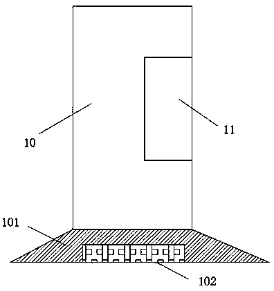
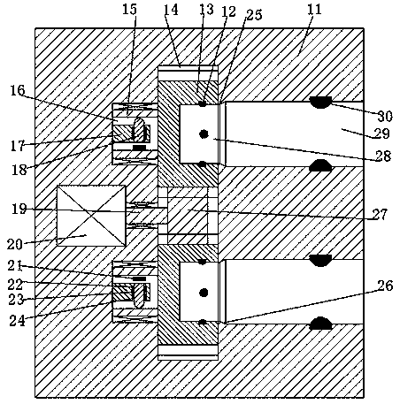
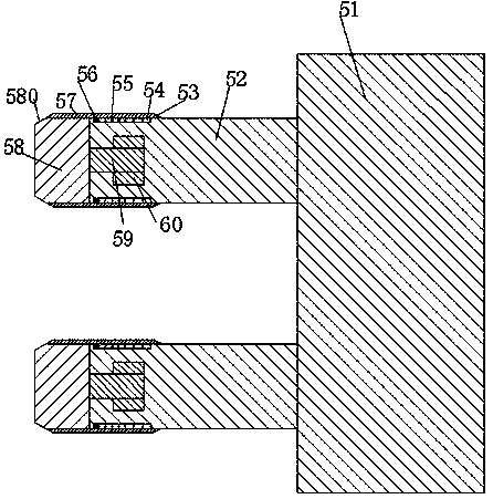
[0028] like Figure 1 to Figure 7 As shown, a new type of intelligent robot charging equipment of the present invention includes a charging pile body 10 and a charging terminal 51 connected to the robot. The bottom of the charging pile body 10 is fixed with a base 101, and the inner bottom of the base 101 is inlaid There is a counterweight lead block 102, and the counterweight lead block 102 is used to increase the bottom weight of the base 1...


PUM


Abstract

The invention discloses novel intelligent robot charging equipment. The novel intelligent robot charging equipment comprises a charging pile body and a charging end socket connected with a robot. A base is fixedly arranged at the bottom part of the charging pile body, and a counterweight lead block is inlaid in the inner bottom part of the base. A charging port is formed in a right end surface ofthe charging pile body, and insertion grooves which are open to the right and are vertically symmetric are formed in the charging port. First contacts are mounted in inner walls of the insertion grooves, left ends of the insertion grooves are provided with convex parts, and placement grooves communicated with the insertion grooves are formed in the left ends of the insertion grooves. First rotaryholes are vertically and symmetrically formed in the left end walls of the placement grooves, rotating sleeves are mounted in the first rotating holes in a rotatable manner, middle end grooves of which left and right ends are communicated are formed in the rotating sleeves, four second contacts are fixed on inner walls of the middle end grooves, tooth-shaped discs that are fixedly connected with the rotating sleeves are arranged in the placement grooves in a vertically symmetric manner, and tooth-shaped wheels connected with the tooth-shaped discs in a matched manner are mounted between the tooth-shaped discs in a rotatable manner.

Description

technical field [0001] The invention relates to the field of intelligent robots, in particular to a novel intelligent robot charging equipment. Background technique [0002] With the advent of the intelligent era, the application of some intelligent robots is becoming more and more extensive. As we all know, intelligent robots use electric energy as their energy source, so they need to be charged in time after the electric energy is consumed. There are many existing robots Charging pile device, but its setting mode is too simple, and the conductive parts inside are relatively set outside. These conductive parts are easily touched by metal rods. Since metal rods can conduct electricity, accidental contact by humans is easy to induce electric shock accidents. In addition, in the traditional technology, the stability of the charging connection of the robot is poor, and it is easy to be affected by the dragging of the charging line, which will cause the plug to be loose, resulti...

Claims


Application Information

Patent Timeline
Patent Type & Authority Applications(China)
IPC IPC(8): H01R13/639H01R13/70H02J7/00
CPCH01R13/701H01R13/639H02J7/0042
Inventor 楼国华
Owner QUZHOU YANHANG MACHINERY TECH CO LTD
Features
  • R&D
  • Intellectual Property
  • Life Sciences
  • Materials
  • Tech Scout
  • Unparalleled Data Quality
  • Higher Quality Content
  • 60% Fewer Hallucinations
Learn More