Supercharge Your Innovation With Domain-Expert AI Agents!

Safe power plug-in device

A plug-in device and power technology, which is applied to the parts, coupling devices, circuits, etc. of the connection device, can solve the problems that the plug cannot be automatically ejected, the power supply connection is unstable, and a large force is applied, and the locking and unlocking operations can be achieved. Simple and convenient, easy and labor-saving to pull out the plug, safe and stable power supply

Inactive Publication Date: 2018-07-03
朱顺华
View PDF0 Cites 0 Cited by
  • Summary
  • Abstract
  • Description
  • Claims
  • Application Information

AI Technical Summary

Problems solved by technology

[0002] At present, the power supply of electrical equipment is mainly to directly insert the plug connected with the electrical equipment into the power supply hole of the socket. Although this cooperation method is simple to operate, the plug can still be pulled out directly after the plug is inserted into the power supply hole. When an accidental kick hits the cable connected between the plug and the electrical equipment, the plug will be detached from the power supply hole, resulting in a sudden power failure of the electrical equipment. Therefore, there is a power supply connection in the existing coordination method The risk of instability is likely to cause damage to electrical equipment due to a sudden power failure. Moreover, the existing plug cannot automatically pop up in this matching method. When the plug is pulled out, a large force needs to be applied, and it is laborious to pull out.

Method used


Image

  • Safe power plug-in device
  • Safe power plug-in device
  • Safe power plug-in device

Examples


Embodiment Construction

[0020] The preferred embodiments of the present invention will be described in detail below in conjunction with the accompanying drawings, so that the advantages and features of the present invention can be more easily understood by those skilled in the art, so as to define the protection scope of the present invention more clearly.

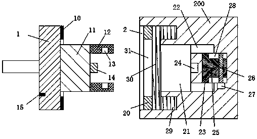
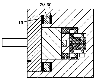
[0021] refer to Figure 1-4 A safe electric plug-in device shown includes a plug body and a seat body, and the plug body includes a first plug block 1 and a second plug block 11, and the second plug block 11 is arranged on the first plug block. In the middle of the right end face of the block 1, a plug 14 is arranged in the middle of the right end face of the second plug block 11, and two plug boards 12 are respectively symmetrically arranged on the front and rear ends of the right end face of the second plug block 11, and the two plugs Two locking holes 13 are respectively symmetrically arranged on the inner end surface of the plate 12, and an a...


PUM


Abstract

The invention discloses a safe power plug-in device comprising an insert body and a seat body. The insert body comprises a first insert block and a second insert block. The second insert block is arranged at the middle of the right end face of the first insert block. The middle of the right end face of the second insert block is provided with a plug. Front and back ends of the right end face of the second insert block are symmetrically provided with two insert plates, and inner side end faces of the two insert plates are symmetrically provided with two locking holes. An annular gasket is arranged on the right end face of the first insert block and the periphery of the second insert block. The seat body comprises a base arranged in a wall. The safe power plug-in device has the advantages ofa simple structure, good power supply stability, safe and reliable operation, reasonable structure design, even if someone accidentally hits a cable connected between the plug and electrical equipment, the plug is not separated from the matching connection with a power supply hole, the locking and unlocking operations of the plug are simple and convenient, and the safe power plug device is suitable for popularization.

Description

technical field [0001] The invention relates to the field of power plugs, in particular to a safe power plug device. Background technique [0002] At present, the power supply of electrical equipment is mainly to directly insert the plug connected with the electrical equipment into the power supply hole of the socket. Although this cooperation method is simple to operate, the plug can still be pulled out directly after the plug is inserted into the power supply hole. When an accidental kick hits the cable connected between the plug and the electrical equipment, the plug will be detached from the power supply hole, resulting in a sudden power failure of the electrical equipment. Therefore, there is a power supply connection in the existing coordination method The risk of instability is likely to cause damage to electrical equipment due to a sudden power failure, and the plug in this matching method cannot automatically pop out, and a large force needs to be applied when the p...

Claims


Application Information

Patent Timeline
IPC IPC(8): H01R13/633H01R13/635H01R13/639H01R13/717
CPCH01R13/633H01R13/635H01R13/639H01R13/717
Inventor 朱顺华朱丹青
Owner 朱顺华
Features
  • R&D
  • Intellectual Property
  • Life Sciences
  • Materials
  • Tech Scout
  • Unparalleled Data Quality
  • Higher Quality Content
  • 60% Fewer Hallucinations
Learn More