A machine tool guide rail unloader

A technology of unloader and guide rail, which is applied in the direction of metal processing machinery parts, metal processing equipment, maintenance and safety accessories, etc., and can solve the problems of general practicability and unadjustable spring force

Active Publication Date: 2019-09-20
太仓鑫祥金属制品有限公司 +1
View PDF1 Cites 0 Cited by
  • Summary
  • Abstract
  • Description
  • Claims
  • Application Information

AI Technical Summary

Problems solved by technology

The elastic force of the spring in this device cannot be adjusted, and the practicability is general

Method used


Image

  • A machine tool guide rail unloader
  • A machine tool guide rail unloader
  • A machine tool guide rail unloader

Examples


specific Embodiment approach 1

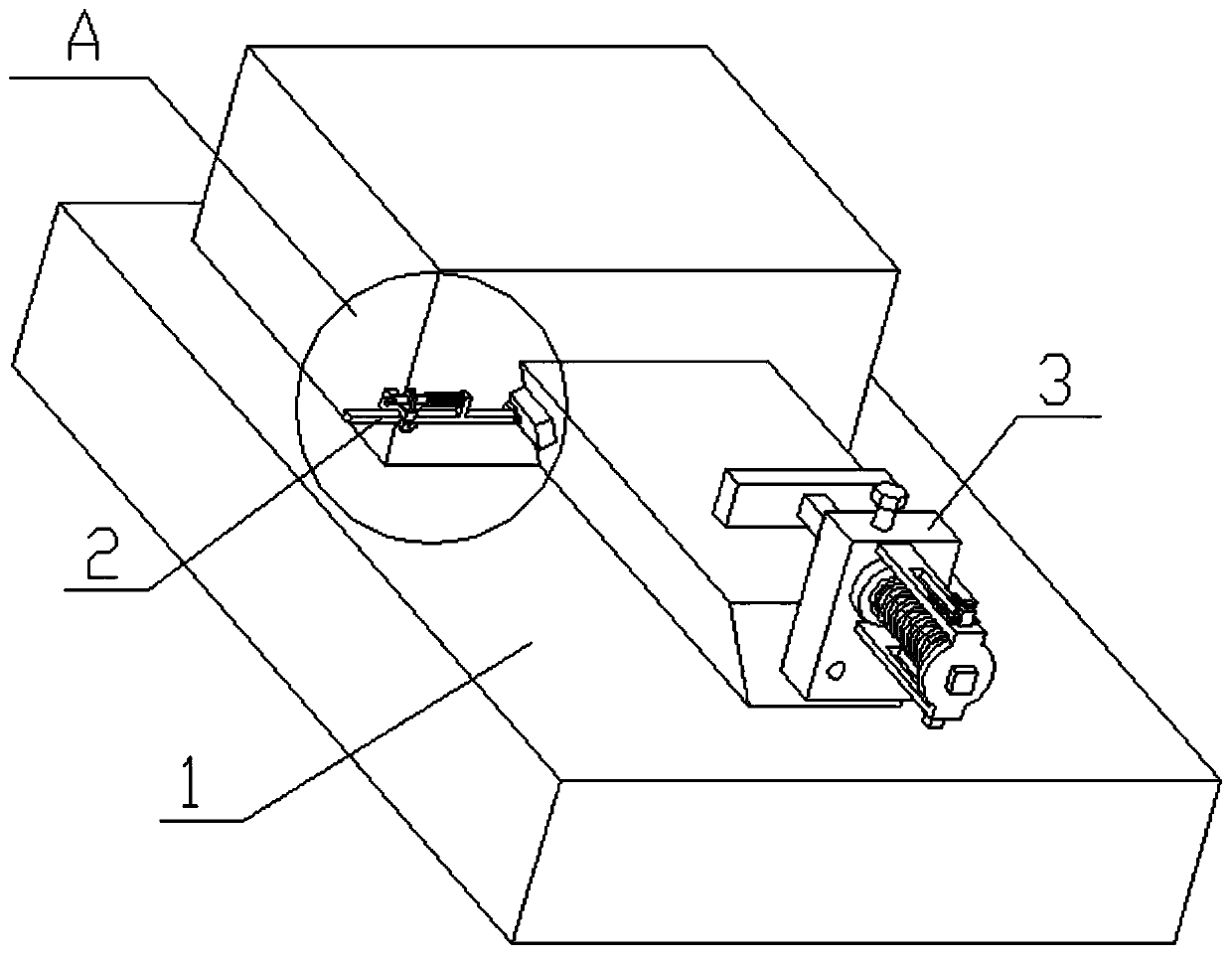
[0031] Combine below Figure 1-13 Describe this embodiment, the present invention relates to the field of mechanical equipment, more specifically a machine tool guide rail unloader, including a carrier plate assembly 1, an unloading assembly I2 and an unloading assembly II3, an unloading assembly I and an unloading assembly II The elastic force of the spring in it can be adjusted to achieve unloading of different strengths.

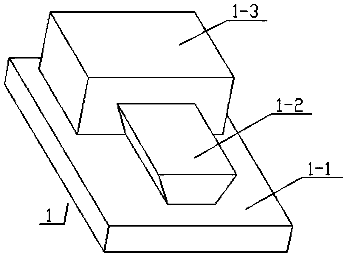
[0032] The carrier board assembly 1 includes a carrier board 1-1, a ladder-shaped slide rail 1-2 and a slider 1-3, the upper end of the carrier board 1-1 is provided with a ladder-shaped slide rail 1-2, and on the ladder-shaped slide rail 1-2 There are sliding parts 1-3 in the sliding connection; the unloading assembly II3 is arranged on the front end of the trapezoidal slide rail 1-2;

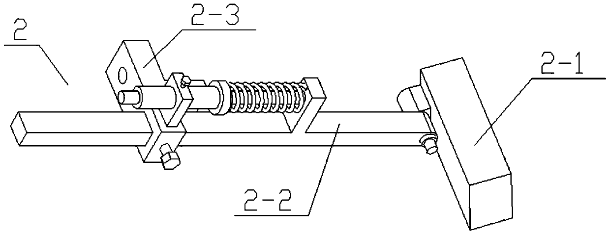
[0033] The unloading assembly I2 includes an unloading plate 2-1, a hinged shaft 2-1-1, a retaining ring 2-1-2, a cross bar 2-2, a circular rod seat 2-2-1, and a spring ...


PUM


Abstract

The invention relates to the field of mechanical equipment, in particular to a machine tool guide rail unloader. The machine tool guide rail unloader comprises a bearing plate component, an unloadingcomponent I and an unloading component II, the elasticity of springs inside the unloading component I and the unloading component II can be adjusted, unloading of different strength can be realized, atrapezoid sliding rail is slidably connected with a sliding part, the unloading component II is arranged at the front end of the trapezoid sliding rail, the unloading component I comprises an unloading pasting plate, a hinge joint shaft, a blocking ring, a horizontal rod, a round plug rod seat, a spring I, a round plug rod and a fixed seat component, the left end of the unloading pasting plate isfixedly connected with the hinge joint shaft, the front end of the hinge joint shaft is connected with the blocking ring through threads, the right end of the horizontal rod is hinged to the hinge joint shaft, the blocking ring is arranged at the front end of the horizontal rod in a blocking manner, the upper end of the horizontal rod is fixedly connected with the round plug rod seat, the left end of the round plug rod seat is fixedly connected with the round plug rod, the round plug rod is connected with the spring I in a sleeved manner, the fixed seat component is arranged on the horizontalrod, and the right end surface of the unloading pasting plate is in fit to the inclined side surface of the left end of the trapezoid sliding rail.

Description

technical field [0001] The invention relates to the field of mechanical equipment, in particular to a machine tool guide rail unloader. Background technique [0002] The application number is CN201710432304.9 for a sliding guide rail unloading device of a machine tool machining center. The invention provides a sliding guide rail unloading device of a machine tool machining center, which includes a sliding part, an unloading block, a blind hole, a spring, a push block, and a screw thread Hole, threaded rod, block, spring 2 and through hole, the blind hole is set on the right end surface inside the slider, the push block is assembled inside the blind hole, the right end of spring one is fixed on the left end face of the push block, and the left end of spring one is fixed on the push block The right end face, the push block and the spring are assembled inside the blind hole. The right end of the threaded rod is fixed on the left end face of the push block. The left end of the t...

Claims


Application Information

Patent Timeline
Patent Type & Authority Patents(China)
IPC IPC(8): B23Q1/01B23Q11/00
Inventor 张勇
Owner 太仓鑫祥金属制品有限公司
Why Eureka
Try Eureka