Gearbox gear shaft chamfering and forming device

A molding device, gearbox technology, applied in positioning devices, turning equipment, clamping and other directions, can solve the problems of wasted labor, limited clamping force, insufficient clamping force, etc., to achieve fully automatic processing, realize feeding and unloading materials, the effect of expanding the scope of use

Active Publication Date: 2014-12-03
浙江祥晋汽车零部件股份有限公司
View PDF7 Cites 13 Cited by
  • Summary
  • Abstract
  • Description
  • Claims
  • Application Information

AI Technical Summary

Problems solved by technology

The centrifugal force clamps the workpiece, although it is easy to process and can realize automatic clamping of the workpiece, but the structure of the fixture is too simple, and its clamping force is limited, so it is easy to have insufficient clamping force, and the workpiece is prone to loosening during cutting. Defective products or accidents
Moreover, although the above-mentioned fixture can automatically clamp the workpiece, it still needs manual feeding and unloading to complete the overall processing of the transmission gear shaft, which not only wastes labor, but also makes the production efficiency still low, which cannot meet the rapid mass production of gear shafts.

Method used


Image

  • Gearbox gear shaft chamfering and forming device
  • Gearbox gear shaft chamfering and forming device
  • Gearbox gear shaft chamfering and forming device

Examples


Embodiment Construction

[0028] The present invention will be further described in detail below with reference to the embodiments of the accompanying drawings.

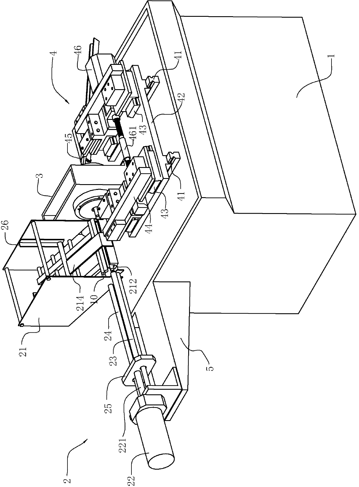
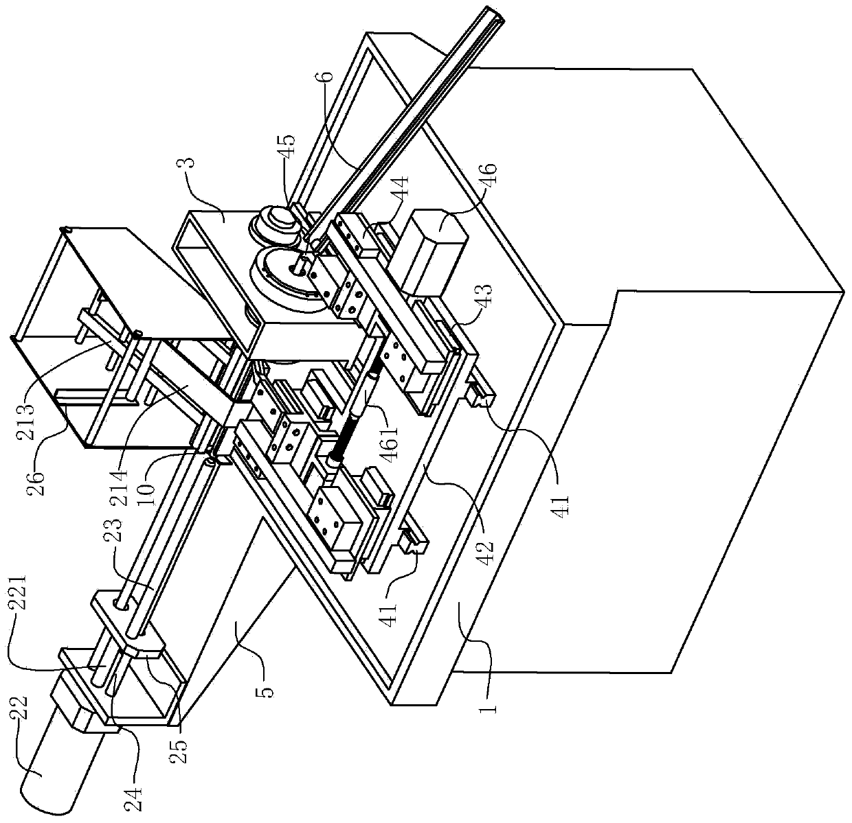
[0029] like Figure 1-2 As shown, the flat-end chamfering forming device of the gearbox gear shaft according to the embodiment of the present invention includes a base 1 , a feeding device 2 and a clamp 3 fixed on the base, and a cutting device 4 located on the base 1 . The feeding device 2 is used for automatic feeding and unloading of the gear shaft 10 , the clamp 3 clamps the gear shaft 10 to be processed, and drives the gear shaft 10 to rotate during cutting, and cooperates with the cutting device 4 to process the end face of the gear shaft 10 the chamfer.

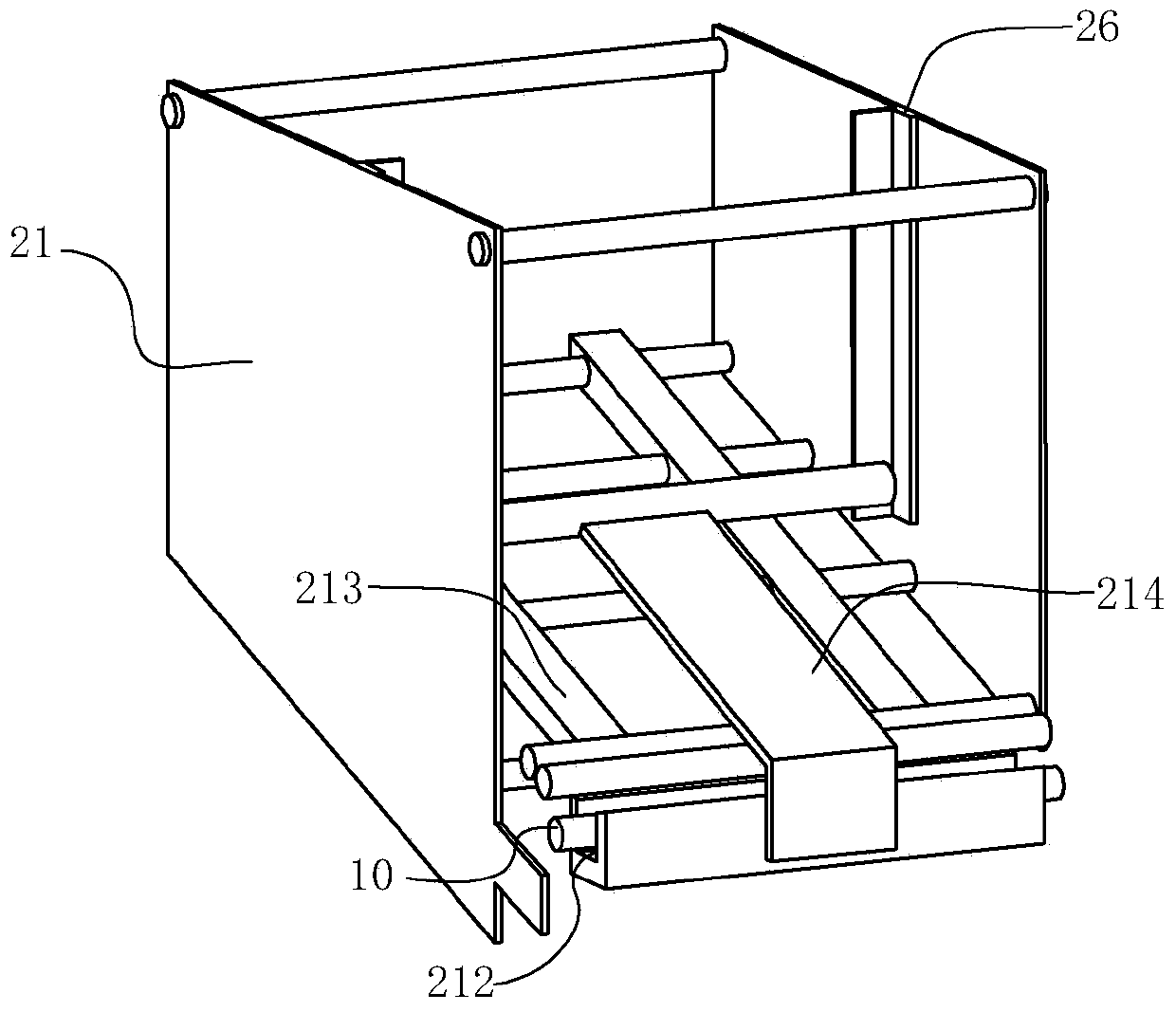
[0030] like Figure 1-4 As shown, the feeding device 2 includes a feeding hopper 21, and a horizontal driving device 22 located on one side of the bottom of the feeding hopper 21. The bottom of the feeding hopper 21 has a discharging port, which is aligned with the The jig 3 on the...


PUM


Abstract

A gearbox gear shaft chamfering and forming device comprises a base, a feed device, a clamp and a cutting device, wherein the feed device, the clamp and the cutting device are fixed on the base. The feed device is capable of automatically inserting gear shafts to be processed into the clamp, the clamp drives the gear shafts to be processed to rotate and clamps the same during rotating, two ends of the gear shafts are exposed out of the clamp and correspond to two cutters on the cutting device, and the cutting device can drive the cutters to move on the horizontal plane and align to ends of the gear shafts. By the gearbox gear shaft chamfering and forming device, the gear shafts can be clamped tightly during cutting and can be unclamped after cutting, thus, automatic feed and discharge of the gear shafts can be realized, and production efficiency is greatly improved. Further, the gear shafts of different sizes can be clamped, and usage range of the gearbox gear shaft chamfering and forming device is broadened.

Description

technical field [0001] The invention relates to a processing device, in particular to a gear shaft forming device for a transmission. Background technique [0002] The gear shaft of the transmission case is an elongated component, and the peripheries of the end faces at both ends thereof are chamfered. Generally, the chamfering process needs to fix the gear shaft, and then rotate the cutting process. For general rotary cutting workpieces, most of them use three-jaw flange clamps. Manually load the workpiece into the fixture and clamp it, and then use the tool to cut the workpiece. This method of manually loading workpieces is time-consuming and labor-intensive, has low work efficiency, cannot meet the requirements of large-scale workpiece processing, and has high requirements on operators. If not very skilled workers operate, it is easy to clamp the workpiece crooked , and then affect the cutting process, so that the defective rate of the product is greatly improved. In a...

Claims


Application Information

Patent Timeline
Patent Type & Authority Applications(China)
IPC IPC(8): B23B5/16B23B15/00B23Q3/00
CPCB23B5/165B23B5/167B23B2220/08B23Q3/064B23Q7/00B23Q7/06
Inventor 童辉吉中全
Owner 浙江祥晋汽车零部件股份有限公司
Why Eureka
Try Eureka