
Flexible clamping device of bent pipe
A technology for flexible clamping and bending of pipes, applied in storage devices, feeding devices, positioning devices, etc., can solve the problems of inconvenient clamping and fixing of curved pipe fittings, and achieve firm clamping, firm clamping, and ensure processing accuracy. Effect
- Summary
- Abstract
- Description
- Claims
- Application Information
AI Technical Summary
Problems solved by technology
Method used
Image

Examples
Embodiment Construction
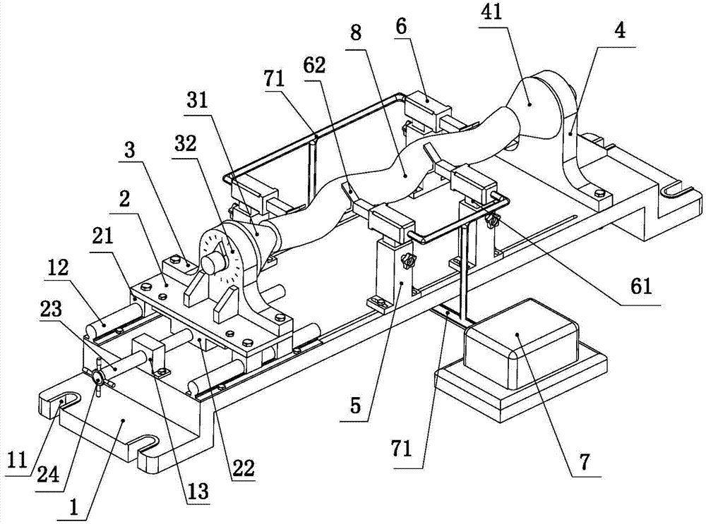
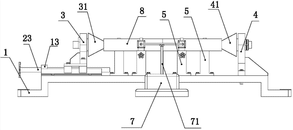
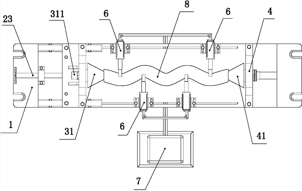
[0020] like Figure 1 to Figure 5 As shown, the present invention comprises frame 1, guide rail 12, movable platform 2, leading screw nut 22, leading screw 23, movable support 3, first thrust member 31, fixed support 4, fixed thrust member 41, column 5. The oil cylinder 6, chuck 62 and hydraulic station 7, the present invention will be described below in conjunction with the accompanying drawings.
[0021] like figure 1 , figure 2 As shown, the frame 1 is the base body of the present invention, and the frame is provided with mounting holes 11, so that the frame can be installed on the machine tool. Two parallel guide rails 12 are arranged on the left end of the frame top, a movable platform 2 is arranged between the two guide rails, a slider 21 is respectively fixed at both ends of the movable platform bottom, and the two sliders are respectively slidably connected with the corresponding guide rails, The relative sliding between the movable platform and the frame is realiz...
PUM
 Abstract
Description
Claims
Application Information