Light microscope and method for image recording using a light microscope

一种光学显微镜、图像的技术,应用在光学显微镜领域,达到短测量时间、少机械运动的效果

Inactive Publication Date: 2018-07-06
CARL ZEISS MICROSCOPY GMBH
View PDF5 Cites 12 Cited by
  • Summary
  • Abstract
  • Description
  • Claims
  • Application Information

AI Technical Summary

Problems solved by technology

But there is the following problem: the sample must be scanned along the z direction relative to the detector
[0019] In the case of the known optical microscopes and methods it is disadvantageous that only a part of the information that can be acquired by the illumination light irradiated by the light source onto the specimen is used

Method used


Image

  • Light microscope and method for image recording using a light microscope
  • Light microscope and method for image recording using a light microscope
  • Light microscope and method for image recording using a light microscope

Examples


Embodiment Construction

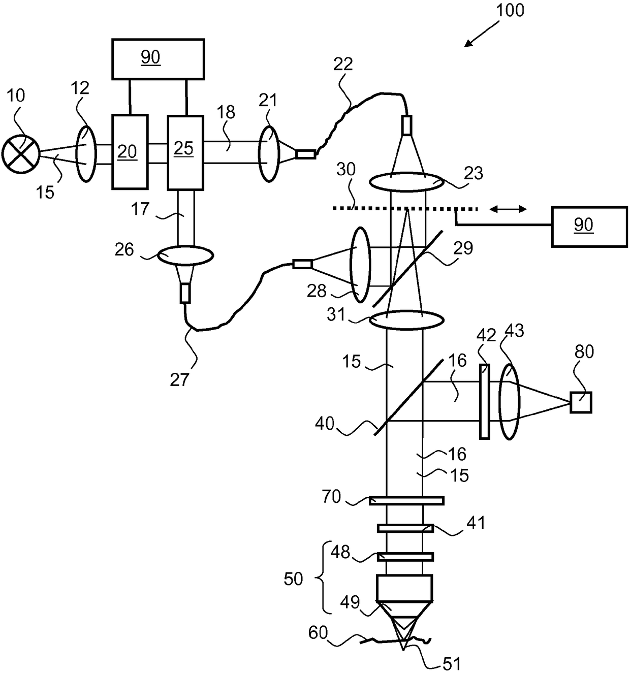
[0059] figure 1 An embodiment of an optical microscope 100 according to the invention is shown. As main components, the optical microscope 100 comprises a polychromatic light source 10 for emitting illumination light 15, a structured element 30 and a focusing device 50 for focusing the illumination light 15 onto a sample 60, by means of which structured The element subjects the illuminating light 15 to a spatial structure. Furthermore, the optical microscope 100 includes a detection device 80 with which the sample light 16 emitted by the sample 60 in the direction of the focusing device 50 is detected. Sample light 16 can be, in particular, irradiation light 15 reflected and / or scattered at sample 16 . In principle, however, sample light 16 can also be fluorescent or phosphorescent light emitted by the sample as a result of absorption of the irradiating light.

[0060] The light source 10 may comprise, for example, one or more lasers, halogen lamps or diodes. The radiated ...


PUM


Abstract

The invention relates to a light microscope and method for image recording using a light microscope. The light microscope comprises a polychromatic light source for emitting illumination light in thedirection of a sample, focussing means for focussing illumination light onto the sample, wherein the focussing means, for generating a depth resolution, have a longitudinal chromatic aberration, and adetection device, which comprises a two-dimensional array of detector elements, for detecting sample light coming from the sample. According to the invention, the light microscope is characterized inthat, for detecting both confocal portions and non-confocal portions of the sample light, a beam path from the sample to the detection device is free of elements for completely masking out non-confocal portions.

Description

[0001] This application is filed on May 16, 2013, and the national application number is 201380025813.X (PCT application number is PCT / EP2013 / 060160), entitled "Optical Microscope and Method for Recording Images Using Optical Microscope" A divisional application of a patent application. technical field [0002] In one aspect, the invention relates to an optical microscope according to the preamble of claim 1 . [0003] In another aspect, the invention relates to a method for recording an image with an optical microscope according to the preamble of claim 16 . Background technique [0004] For the characterization of technical surfaces, and especially for the derivation of roughness measurements and topography, confocal microscopy is used today as a standard method. This method is for example described in M.Rahlwes, J.Seewig "Optical measurement of technical surfaces (Optisches Messen technischer )”, Beuth Verlag, Berlin, 2009. [0005] In many confocal systems, the sampl...

Claims


Application Information

Patent Timeline
Patent Type & Authority Applications(China)
IPC IPC(8): G02B21/00G01B11/25
CPCG02B21/0028G02B21/0032G02B21/0044G02B21/0064G02B21/367G01B2210/50G01B9/04G01B11/25G01B21/32G02B21/0036G02B21/24G01N2021/6463G01N2021/6419G01N2021/6421G01B9/02042G02B21/006G02B21/0068G02B21/008G02B21/0092G02B21/08G02B21/14G02B21/18
Inventor 赫尔穆特·利珀特拉尔夫·内茨蒂莫·安胡特尼尔斯·兰霍尔茨马蒂亚斯·朗霍斯特
Owner CARL ZEISS MICROSCOPY GMBH
Why Eureka
Try Eureka