Unlock instant, AI-driven research and patent intelligence for your innovation.
Imaging device, printing system, printing device, image printing method, and storage medium having stored thereon program controlling the image printing method
What is Al technical title?
Al technical title is built by PatSnap Al team. It summarizes the technical point description of the patent document.
a technology of image printing and printing method, which is applied in the direction of image enhancement, television systems, instruments, etc., can solve the problems of difficult operation and problematic photography for users, and achieve the effect of relieving users of bother
Inactive Publication Date: 2009-06-04
PANASONIC CORP
View PDF4 Cites 93 Cited by
Summary
Abstract
Description
Claims
Application Information
AI Technical Summary
This helps you quickly interpret patents by identifying the three key elements:
Problems solved by technology
Method used
Benefits of technology
[0035]As described above, according to the present invention, it is possible to provide a printing system, a printing device, a printing method, and a storage medium having stored thereon a program for controlling the printing method, which are capable of determining whether or not a residual blurring amount is at a predetermined level depending on a printing paper size, and further displaying a recommended print size corresponding to the residual blurring amount, thereby relieving a user of the bother of determining which size is appropriate for printing.
Problems solved by technology
That is, the operation is not easy but problematic for the photographer or the like if he / she is unaccustomed to the personal computer.
Method used
Image
Click on the blue label to locate the original text in one second.
Reading with bidirectional positioning of images and text.
Examples
first embodiment
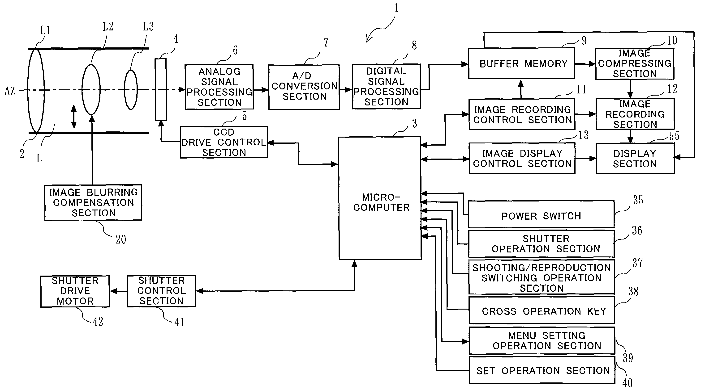
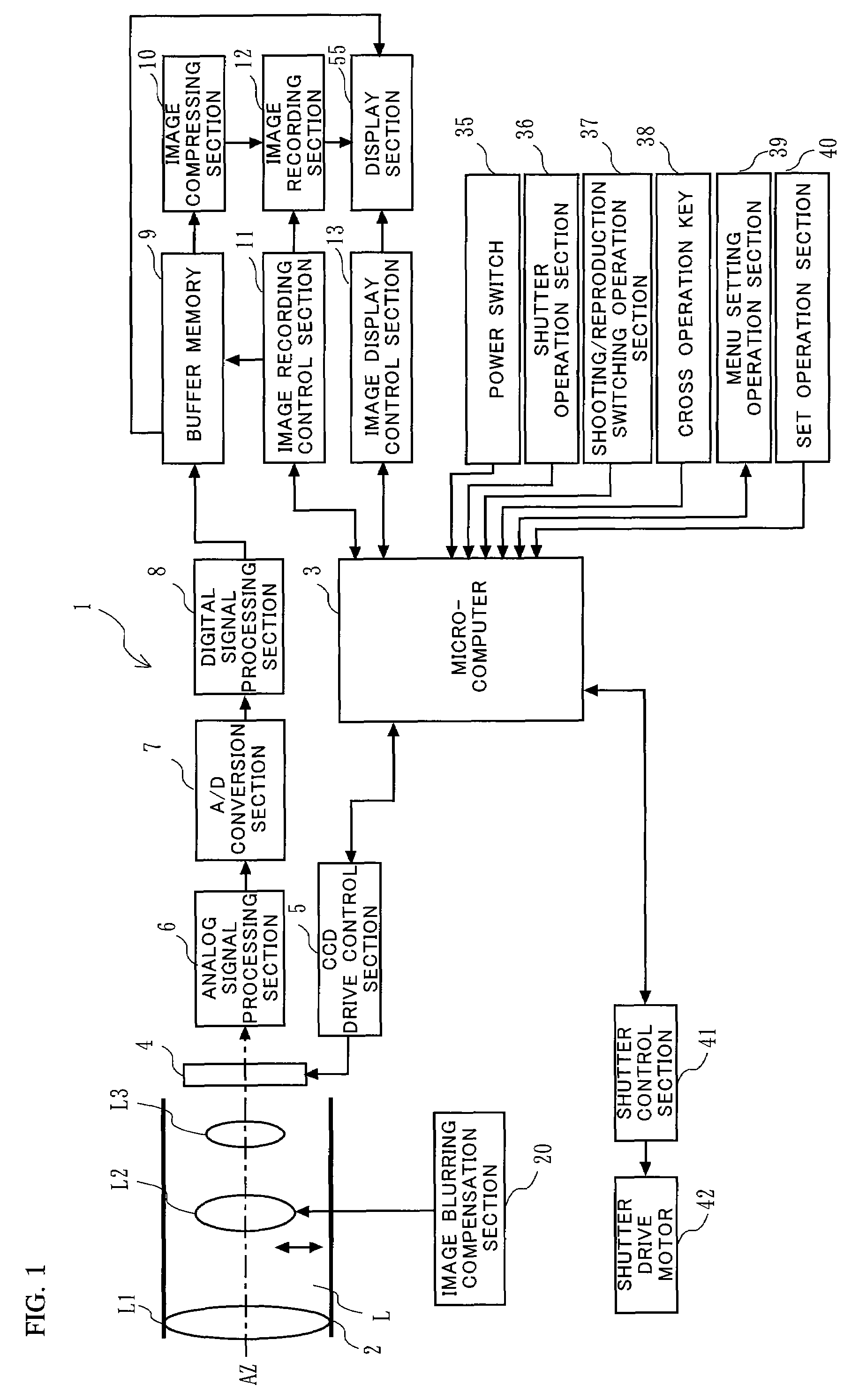
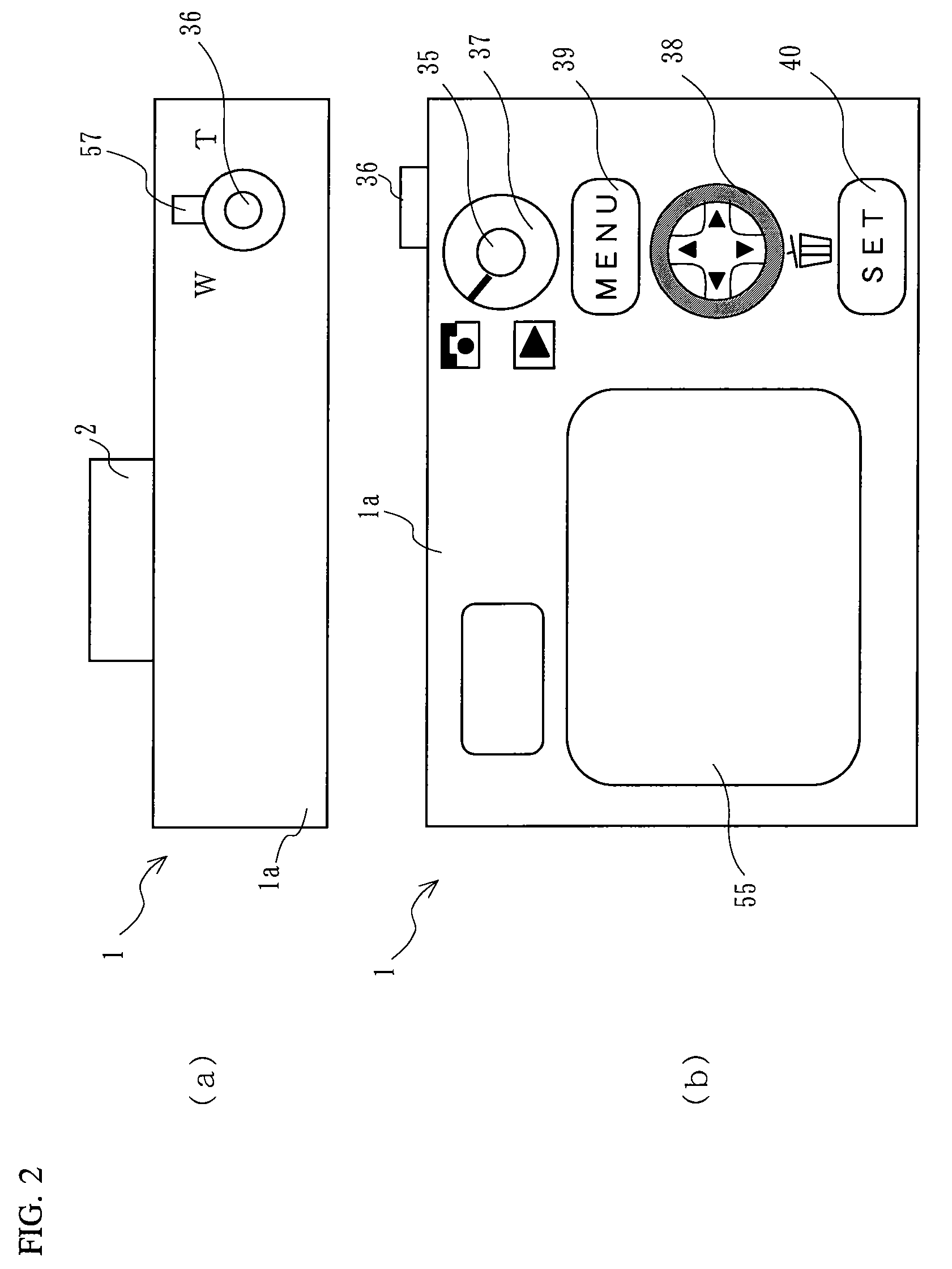
[0105]Hereinafter, with reference to FIGS. 1, 2, 3, 4, 5, 6, 7, 8, 9, and 10, a first embodiment of the present invention will be described. First, with reference to FIG. 1, a digital camera configured as the first embodiment of the present invention will be described. The digital camera 1 includes an imaging optical system L, a microcomputer 3, an imaging sensor 4, a CCD drive control section 5, an analog signalprocessing section 6, an A / D conversion section 7, a digital signalprocessing section 8, a buffer memory 9, an image compressing section 10, an image recording control section 11, an image recording section 12, an image display control section 13, an image blurring compensation mechanism 20, a power switch 35, a shutter operation section 36, a shooting / reproduction switching operation section 37, a cross operation key 38, a SET operation key 40, a shutter control section 41, and a shutterdrive motor 42.
[0106]The imaging optical system L is constituted of three
[0107]lens u...
second embodiment
[0169]Hereinafter, with reference to FIGS. 14, 15, 16 and 17, a second embodiment of the present invention will be described. Although a digital camera according to the present embodiment is configured in the same manner as the camera 1 according to the above-described first embodiment, an operation of a printing process thereof is different. Hereinafter, the operation will be described.
[0170]FIG. 14 shows a flowchart illustrating details of the printing process of a shot image. In steps S2, S3, S4, S8, and S9 shown in FIG. 14, basically the same processes as those in corresponding steps shown in FIG. 10 are performed. In other words, processes additionally adopted in the present embodiment are performed in steps S14, S15, S16, S17, and S18 shown in FIG. 14.
[0171]Specifically, after the microcomputer 3 determines that a reproduction mode is selected by using a shooting / reproduction switching operation section 37, and that a MENU setting control section 39 has been pressed, the micro...
PUM
Abstract
In the case of printing while a digital camera is directly connected to a printer, it has been impossible to determine to what extent image blurring affects a print image. In an imaging device, a detection section (17A) detects blurring. An image blurring compensation section (15A) compensates image blurring. A compensation amount detection section (16) detects an image blurring compensation amount. A calculation section (19A) calculates a residual blurring amount by subtracting the image blurring compensation amount from an image blurring amount. An image recording section (12) records an image signal, as a shot image, together with the residual blurring amount. A print size specification section (91) specifies a print size of the shot image and stores a tolerance (β) of the residual blurring amount with respect to the print size. And, a determination section (80) determines whether or not the residual blurring amount is equal to or greater than the tolerance with respect to a predetermined print size, and issues a warning to a photographer or the like in the case where the residual blurring amount is greater than the tolerance.
Description
TECHNICAL FIELD[0001]The present invention relates to a method for printing an image shot by an imaging device, and more particularly to an imaging device, a printing device, and a printing system which control a printing method of a shot image, an image printing method, and a storage medium having stored thereon a control program of the image printing method.BACKGROUND ART[0002]Recently, an imaging sensor such as a CCD (Charge Coupled Device) and a CMOS (Complementary Metal-OxideSemiconductor), and a signalprocessing circuit are increasingly improved in terms of integration density and come to be available inexpensively. Accordingly, an imaging device typified by a digital still camera and a digital video camera (hereinafter jointly referred to as a “digital camera”), which are capable of converting an optical image of an object into an electrical image signal by using such an imaging sensor, is rapidly growing popular.[0003]In the case where an image shot with a digital camera i...
Claims
Application Information
Patent Timeline
Application Date:The date an application was filed.
Publication Date:The date a patent or application was officially published.
First Publication Date:The earliest publication date of a patent with the same application number.
Issue Date:Publication date of the patent grant document.
PCT Entry Date:The Entry date of PCT National Phase.
Estimated Expiry Date:The statutory expiry date of a patent right according to the Patent Law, and it is the longest term of protection that the patent right can achieve without the termination of the patent right due to other reasons(Term extension factor has been taken into account ).
Invalid Date:Actual expiry date is based on effective date or publication date of legal transaction data of invalid patent.
Patent Type & Authority Applications(United States)