
Imaging device, printing system, printing device, image printing method, and storage medium having stored thereon program controlling the image printing method

a technology of image printing and printing method, which is applied in the direction of image enhancement, television systems, instruments, etc., can solve the problems of difficult operation and problematic photography for users, and achieve the effect of relieving users of bother

Inactive Publication Date: 2011-08-16
PANASONIC CORP
View PDF10 Cites 1 Cited by
  • Summary
  • Abstract
  • Description
  • Claims
  • Application Information

AI Technical Summary

Benefits of technology

"The present invention aims to provide an imaging device, printing system, printing device, and printing method that can print with a tolerable blurring amount corresponding to a print size. This is a problem because conventional imaging devices have difficulty in determining if a shot image is blurred without actually printing. The invention solves this problem by using the blurring amount as a criterion for printing, and ensures that a blurred image is not printed out as an unsatisfactory result. The invention also adapts to different paper sizes and allows for the determination of the blurring amount in advance, making the printing process more convenient for photographers or other users."

Problems solved by technology

That is, the operation is not easy but problematic for the photographer or the like if he / she is unaccustomed to the personal computer.

Method used


Image

  • Imaging device, printing system, printing device, image printing method, and storage medium having stored thereon program controlling the image printing method
  • Imaging device, printing system, printing device, image printing method, and storage medium having stored thereon program controlling the image printing method
  • Imaging device, printing system, printing device, image printing method, and storage medium having stored thereon program controlling the image printing method

Examples


first embodiment

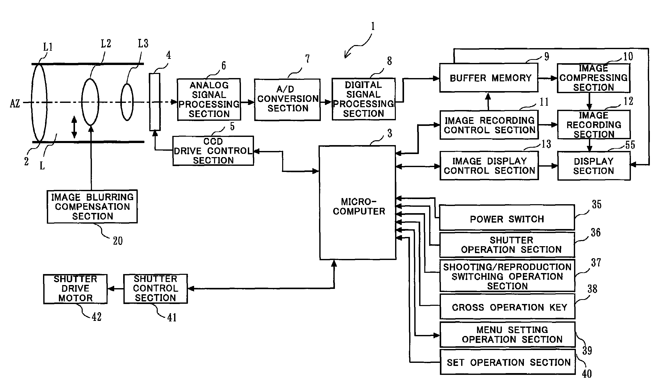
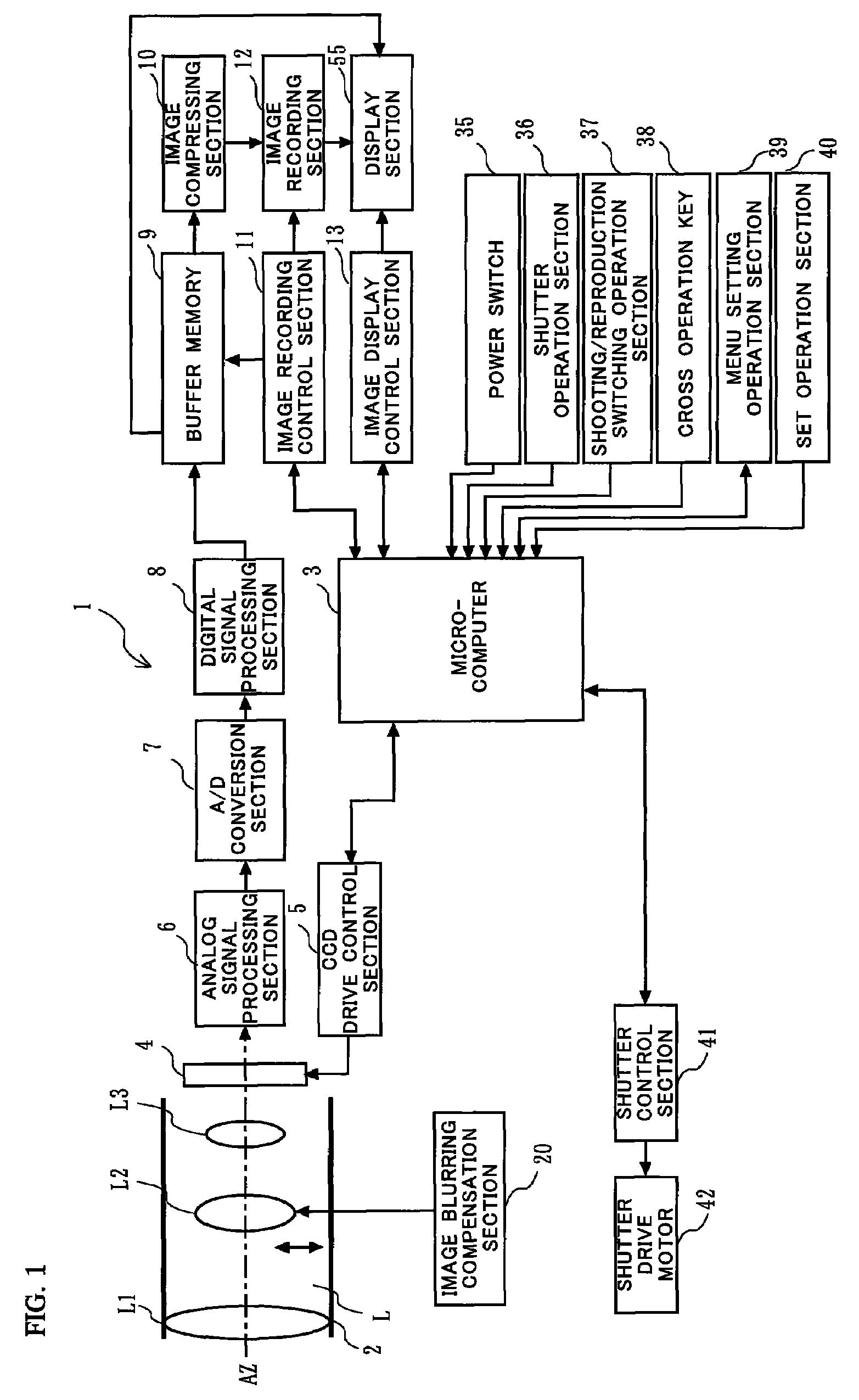
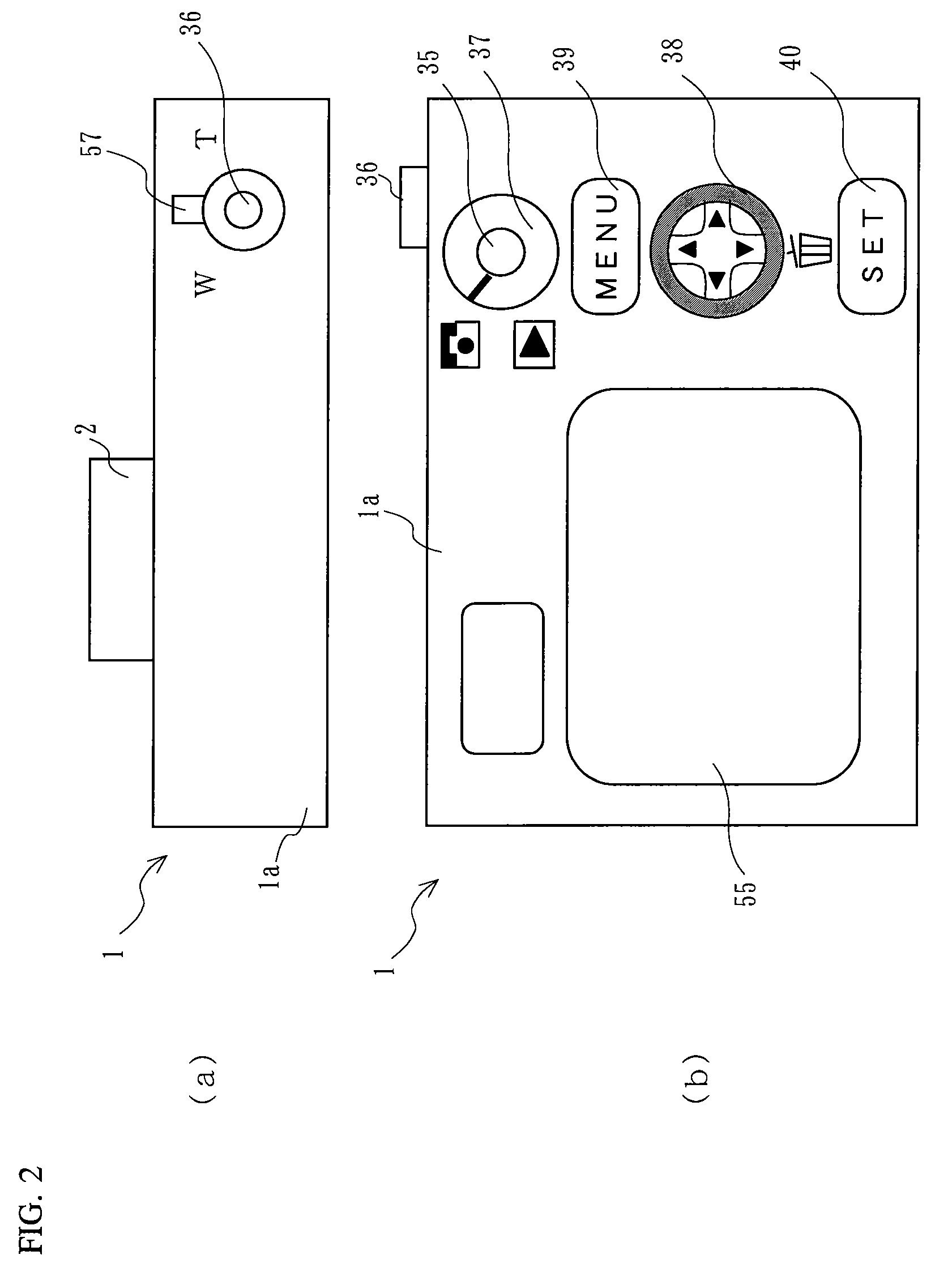
[0109]Hereinafter, with reference to FIGS. 1, 2, 3, 4, 5, 6, 7, 8, 9, and 10, a first embodiment of the present invention will be described. First, with reference to FIG. 1, a digital camera configured as the first embodiment of the present invention will be described. The digital camera 1 includes an imaging optical system L, a microcomputer 3, an imaging sensor 4, a CCD drive control section 5, an analog signal processing section 6, an A / D conversion section 7, a digital signal processing section 8, a buffer memory 9, an image compressing section 10, an image recording control section 11, an image recording section 12, an image display control section 13, an image blurring compensation mechanism 20, a power switch 35, a shutter operation section 36, a shooting / reproduction switching operation section 37, a cross operation key 38, a SET operation key 40, a shutter control section 41, and a shutter drive motor 42.

[0110]The imaging optical system L is constituted of three lens units,...

second embodiment

[0172]Hereinafter, with reference to FIGS. 14, 15, 16 and 17, a second embodiment of the present invention will be described. Although a digital camera according to the present embodiment is configured in the same manner as the camera 1 according to the above-described first embodiment, an operation of a printing process thereof is different. Hereinafter, the operation will be described.

[0173]FIG. 14 shows a flowchart illustrating details of the printing process of a shot image. In steps S2, S3, S4, S8, and S9 shown in FIG. 14, basically the same processes as those in corresponding steps shown in FIG. 10 are performed. In other words, processes additionally adopted in the present embodiment are performed in steps S14, S15, S16, S17, and S18 shown in FIG. 14.

[0174]Specifically, after the microcomputer 3 determines that a reproduction mode is selected by using a shooting / reproduction switching operation section 37, and that a MENU setting control section 39 has been pressed, the micro...


PUM


Abstract

In the case of printing while a digital camera is directly connected to a printer, it has been impossible to determine to what extent image blurring affects a print image. In an imaging device, a detection section (17A) detects blurring. An image blurring compensation section (15A) compensates image blurring. A compensation amount detection section (16) detects an image blurring compensation amount. A calculation section (19A) calculates a residual blurring amount by subtracting the image blurring compensation amount from an image blurring amount. An image recording section (12) records an image signal, as a shot image, together with the residual blurring amount. A print size specification section (91) specifies a print size of the shot image and stores a tolerance (β) of the residual blurring amount with respect to the print size. And, a determination section (80) determines whether or not the residual blurring amount is equal to or greater than the tolerance with respect to a predetermined print size, and issues a warning to a photographer or the like in the case where the residual blurring amount is greater than the tolerance.

Description

RELATED APPLICATIONS[0001]This application is the U.S. National Phase under 35 U.S.C. §371 of International Application No. PCT / JP2006 / 302807, filed on Feb. 17, 2006, which in turn claims the benefit of Japanese Application No. 2005-112483, filed on Apr. 8, 2005 and Japanese Application No. 2005-209519, filed on Jul. 20, 2005, the disclosure of which Applications are incorporated by reference herein.TECHNICAL FIELD[0002]The present invention relates to a method for printing an image shot by an imaging device, and more particularly to an imaging device, a printing device, and a printing system which control a printing method of a shot image, an image printing method, and a storage medium having stored thereon a control program of the image printing method.BACKGROUND ART[0003]Recently, an imaging sensor such as a CCD (Charge Coupled Device) and a CMOS (Complementary Metal-Oxide Semiconductor), and a signal processing circuit are increasingly improved in terms of integration density an...

Claims


Application Information

Patent Timeline
Patent Type & Authority Patents(United States)
IPC IPC(8): G06K15/02H04N1/409
CPCB41J2/17513B41J2/17553B41J29/38H04N1/00278H04N1/00427H04N1/00442H04N1/00453H04N1/00458H04N1/00461H04N1/00482H04N1/2112H04N1/2323H04N1/233H04N1/2338H04N1/2353H04N1/2392H04N1/32128H04N5/23248H04N5/23254H04N5/772H04N5/765H04N2101/00H04N2201/0084H04N2201/3242H04N2201/3252H04N23/6811H04N23/68
Inventor YUMIKI, NAOTOHONJO, KENICHI
Owner PANASONIC CORP
Learn More