3D projection with image recording

a 3d projection and image technology, applied in the field of image recording, can solve the problems of preventing the proper alignment of the tool with the laser point, the safety of the laser light used for image recording, and the inability to accurately align the tool, so as to enhance the flexibility of large-scale manufacturing processes, reduce the cost, and avoid the effect of affecting the quality of the obj

Active Publication Date: 2005-08-30
FARO TECH INC
View PDF31 Cites 91 Cited by
  • Summary
  • Abstract
  • Description
  • Claims
  • Application Information

AI Technical Summary

Benefits of technology

[0016]1) Template imaging mode: rapid beam movement to generate a glowing template with high refresh rate on the surface of the object. Beam speed is adequate for producing an image perceptible by a viewer as a solid pattern but it is too high for proper exposing the photosensitive material on the surface of the object.
[0020]The object has a layer of a photosensitive material applied on at least a portion of its outer surface. The laser projector is positioned so that its output beam can 1) guide the placement of this layer on the object and / or 2) provide a sufficient dose density of light energy to the layer to record the projected image in the layer.

Problems solved by technology

In most cases the laser light used for image recording is not eye safe, and the system is usually contained in an enclosure.
However, in such material processing applications the laser beam would be blocked by the material processing tools, fixtures, and workers, thus preventing proper alignment of the tool with the point aimed by the laser.

Method used


Image

  • 3D projection with image recording
  • 3D projection with image recording
  • 3D projection with image recording

Examples


Embodiment Construction

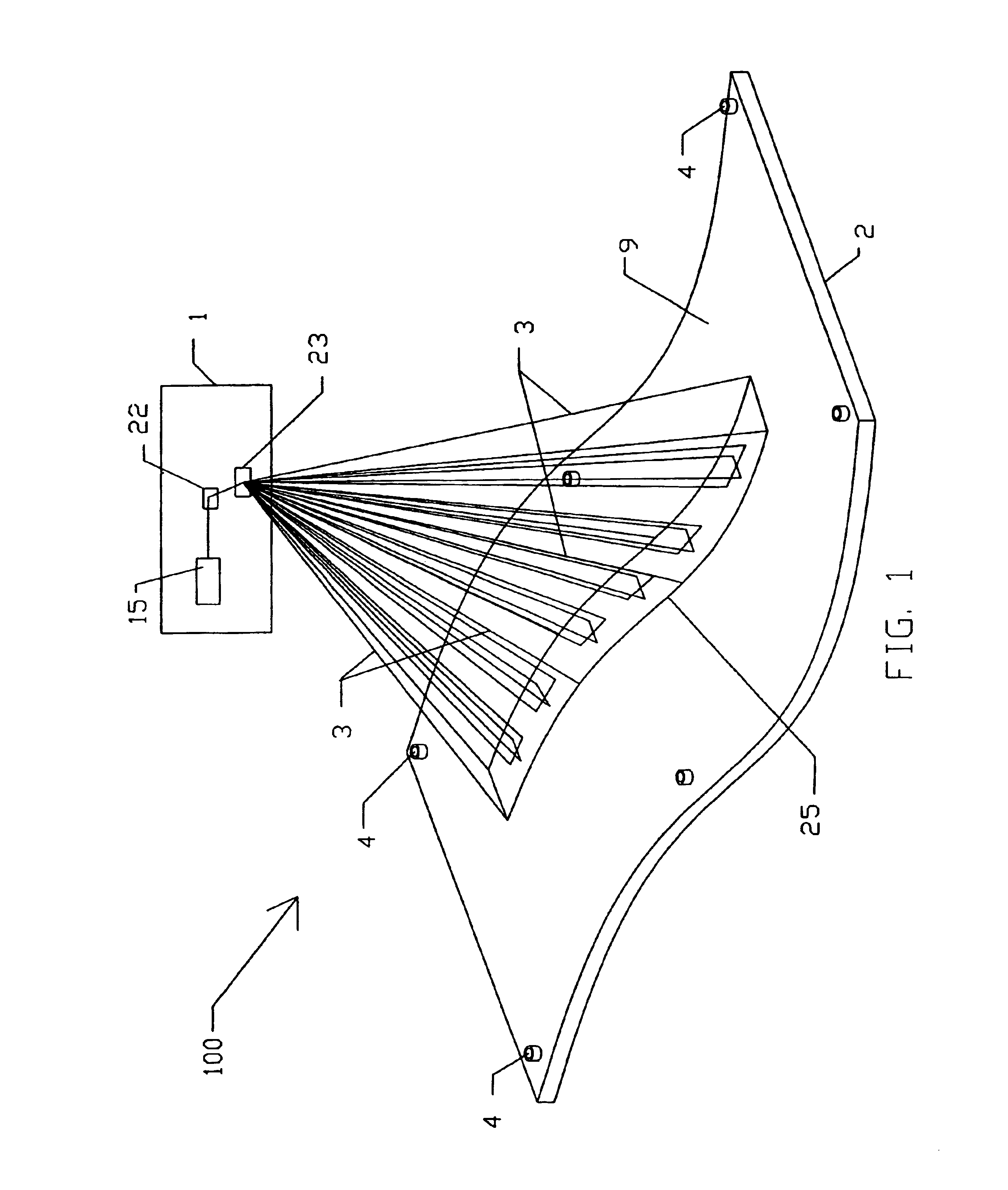
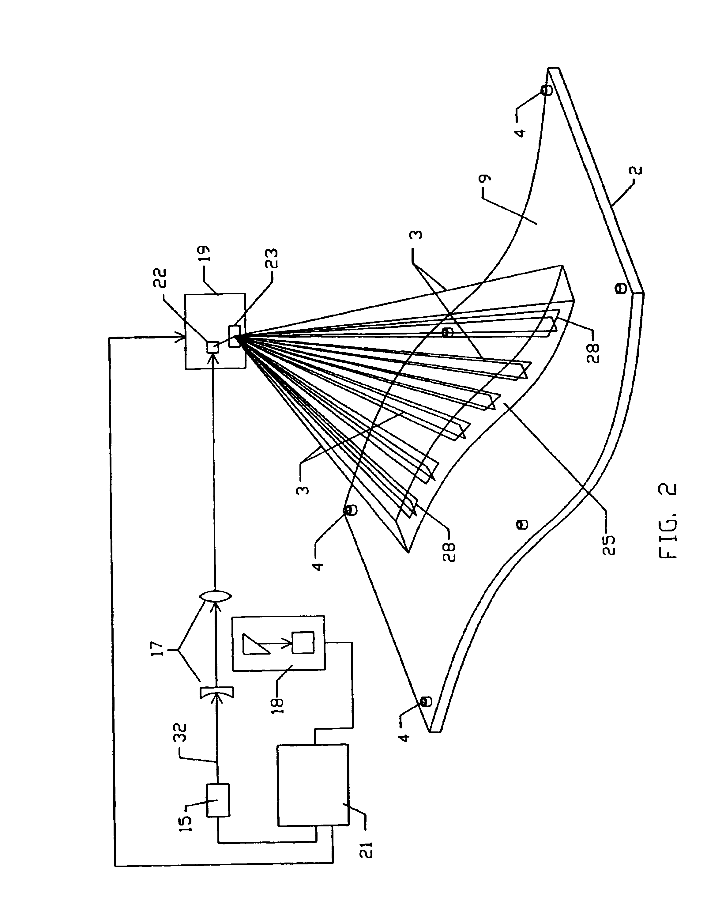
[0043]FIG. 1 shows a 3D light projection system 100 according to the present invention that directs a light beam 3 at a given wavelength onto a facing outer surface 9 of a 3D object 2. A layer 25 of a photosensitive material is applied over a defined area of the surface 9. The light projector 1 is preferably a 3D laser projector shown in a more detailed schematic form in FIG. 2. The projector 1 has a laser 15, a laser beam expanding and focusing optical system 17 for shaping the laser beam 32, an optical feedback device 18, a two-axis beam steering device 19 for directing the output beam 3 onto the object surface 9, and a control system 21 for controlling the laser beam power level and controlling the beam steering device 19. The beam steering device 19 preferably includes X mirror 22 and Y mirror 23 mounted on shafts of galvanometer servo motors (not shown). Rotational movement of the X and Y mirrors rapidly directs the beam 3 over a defined surface area. The control system 21 actu...


PUM


Abstract

An apparatus and method for recording an image on the surface of a 3D object uses a laser projector that scans a light beam over the surface in an image pattern. The projector operates in a template imaging mode and an image recording mode where the beam scans at a speed that in a single pass / scan mode is typically four to five orders of magnitude slower than in the template imaging mode. A layer of a photosensitive material is applied to the surface of the object either partially or fully. Projection in the template imaging mode can guide the applying. The layer is substantially insensitive to ambient light for at least a period of time necessary to perform a desired processing step on the object. The layer has a maximum spectral sensitivity in the vicinity of the wavelength of the laser light beam. In one or multiple passes of the beam over the image pattern operating in the image record mode, the accumulated light energy dose density is sufficient to react the material and record the image.

Description

CROSS REFERENCE TO RELATED APPLICATION[0001]This application claims priority under 35 USC 119(e) of U.S. Provisional Application Ser. No. 60 / 501,536 filed Sep. 8, 2003, the disclosure of which is incorporated herein by reference.BACKGROUND OF THE INVENTION[0002]This invention relates in general to imaging systems. More specifically, it relates to a laser projection system that records a visible image on a three-dimensional object.[0003]It is known to use lasers to project and record images onto objects in applications such as semiconductor manufacture, photocopying, medical imaging, and printers. In these applications, the geometry is typically well controlled and fixed. The projected light beam does not guide the placement of a three-dimensional (“3D”) object, and the system typically has optical components that compensate for the well-defined curvature(s) of the object, e.g. a cylindrical drum. Nor is there optical feedback from the object back to the projecting laser. In most cas...

Claims


Application Information

Patent Timeline
Patent Type & Authority Patents(United States)
IPC IPC(8): G06K9/00G03B21/14G03B21/00G03B21/26G03B35/00G06T
CPCG03B21/00G03B35/00
Inventor KAUFMAN, STEVEN P.SAVIKOVSKY, ARKADY
Owner FARO TECH INC
Why Eureka
Try Eureka