Method and apparatus for providing a pulse width modulation sequence in a liquid crystal display

a liquid crystal display and pulse width technology, applied in the direction of instruments, computing, electric digital data processing, etc., can solve the problems of limiting the available bandwidth for writing data to the display, the visible artifact in an image, and the limitation of the refresh rate, so as to improve the refresh rate, increase the refresh rate, and improve the effect of several aspects of the video display

Inactive Publication Date: 2006-03-30
OMNIVISION TECH INC
View PDF10 Cites 32 Cited by
  • Summary
  • Abstract
  • Description
  • Claims
  • Application Information

AI Technical Summary

Benefits of technology

[0013] The present invention overcomes the problems discussed above in relation to the prior art. An object of the invention is to increase the refresh rate in a liquid crystal display apparatus, thereby achieving the advantages associated with an increased refresh rate, without significantly adversely effecting other aspects of the display or the operation of the LCD apparatus. Additional advantages include improvements in several aspects of the video display.

Problems solved by technology

It is known in the art that differing signals on adjacent pixel cells can cause visible artifacts in an image.
A number of other undesirable artifacts can also be present in an image presented from an LCD display.
However, the available bandwidth for writing data to the display is a limitation on the refresh rate.
However, it should be noted that the method of Wakitani, et al. will never result in a large plurality of equally weighted bits.
Therefore, while Wakitani, et al. does provide some similar advantage to that of the thermometer bits of Worley, III et al., it does not provide as great an advantage in that regard as does the prior art of Worley, III et al.

Method used


Image

  • Method and apparatus for providing a pulse width modulation sequence in a liquid crystal display
  • Method and apparatus for providing a pulse width modulation sequence in a liquid crystal display
  • Method and apparatus for providing a pulse width modulation sequence in a liquid crystal display

Examples


Embodiment Construction

[0025] This invention is described in the following description with reference to the Figures, in which like numbers represent the same or similar elements. While this invention is described in terms of modes for achieving this invention's objectives, it will be appreciated by those skilled in the art that variations may be accomplished in view of these teachings without deviating from the spirit or scope of the present invention. For example, all or part of the present invention may be implemented in software, by dedicated driver circuitry, or by some combination thereof.

[0026] The embodiments and variations of the invention described herein, and / or shown in the drawings, are presented by way of example only and are not limiting as to the scope of the invention. Unless otherwise specifically stated, individual aspects and components of the invention may be omitted or modified, or may have substituted therefore known equivalents, or as yet unknown substitutes such as may be develop...


PUM


Abstract

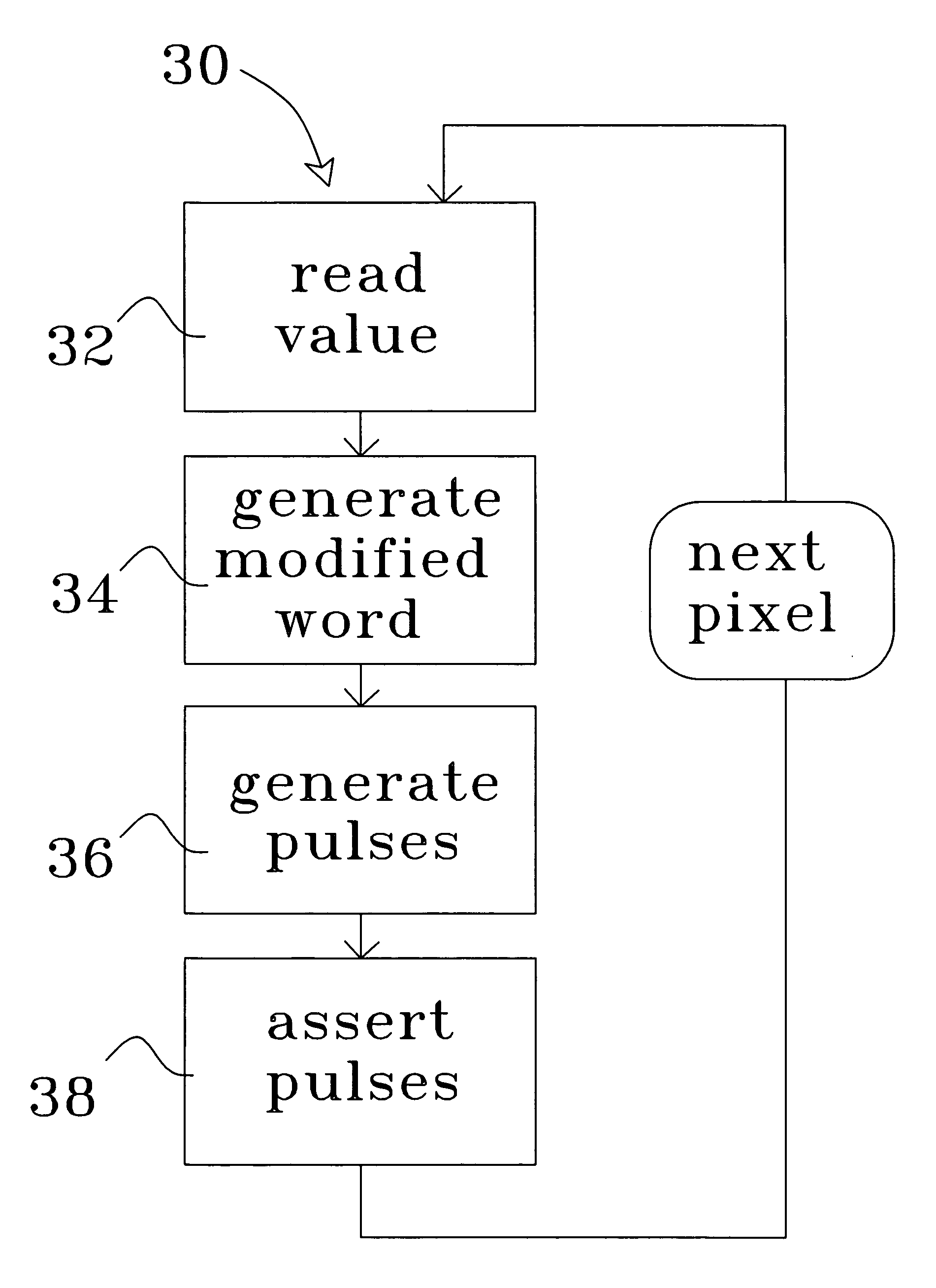
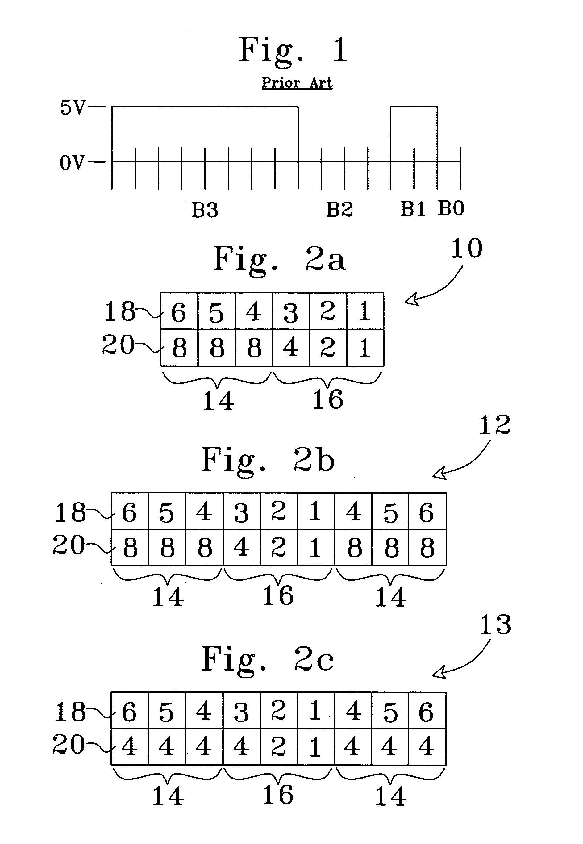
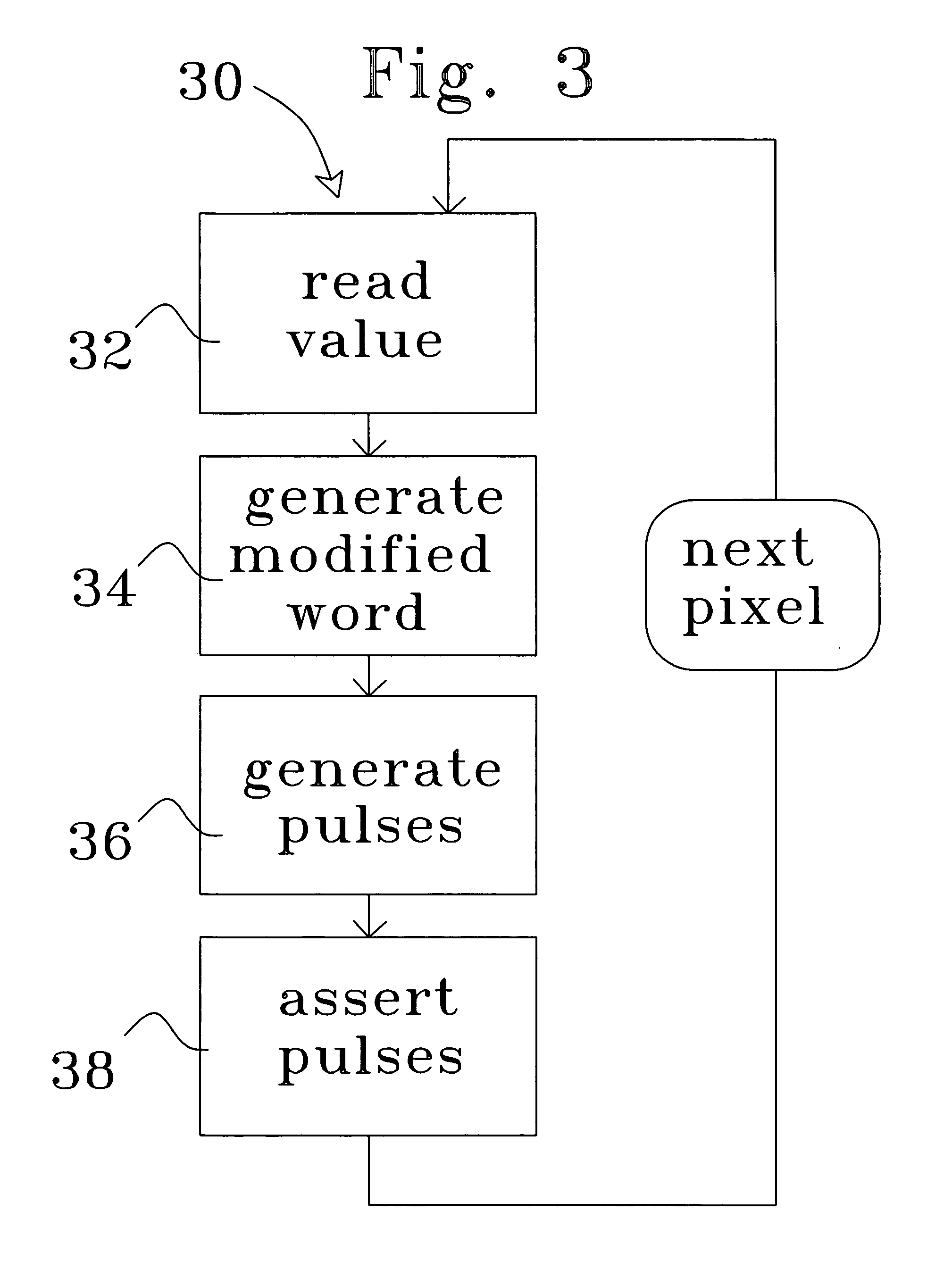
A method for converting a compound data word 10 into a modified data word (12). The compound data word (10) has a plurality of equally weighted thermometer data bits (14) and a plurality of binary weighted data bits (16). The thermometer data bits (14) are repeated in the modified data word (12). In one embodiment, the thermometer data bits (14) are asserted first, then the binary weighted data bits (16), and then the thermometer data bits (14) again, with the second assertion of the thermometer data bits (14) being in reverse order as compared to the first assertion thereof. The weight of the thermometer data bits (14) is optionally changed to keep the relative weighting of the thermometer data bits (14) and the binary weighted data bits (16) unchanged. A display driver circuit (53) in a video display apparatus (50) has a modified data generator (54) for generating the modified data words (12), and a pulse generation and routing circuitry (56) for generating pulses and providing the pulses to a plurality of pixel electrodes (58) of a display (60).

Description

BACKGROUND OF THE INVENTION [0001] 1. Field of the Invention [0002] This invention relates generally to liquid crystal display devices, and more particularly to a method and apparatus for driving a display device, which will reduce undesirable artifacts such as flicker. A predominant current usage of the inventive pulse width modulation sequence is for the improvement of liquid crystal display devices used for displaying dynamic images, which require rapid and frequent updating of the image data. [0003] 2. Description of the Background Art [0004] A liquid crystal display apparatus includes a great plurality of pixel storage elements, generally at least one for each pixel of the display. The pixel storage elements accept and hold, for a period of time, a voltage. The voltage from each pixel storage element is provided to a corresponding pixel electrode, and the intensity of the display on that pixel is a function of that voltage. For example, the liquid crystal material in the displa...

Claims


Application Information

Patent Timeline
Patent Type & Authority Applications(United States)
IPC IPC(8): G09G5/10
CPCG09G3/2029G09G2320/0247G09G3/2033
Inventor NG, SUNNY YAT-SAN
Owner OMNIVISION TECH INC
Why Eureka
Try Eureka