Driving a bi-stable matrix display device

Inactive Publication Date: 2006-03-09
KONINKLIJKE PHILIPS ELECTRONICS NV
View PDF7 Cites 28 Cited by
  • Summary
  • Abstract
  • Description
  • Claims
  • Application Information

AI Technical Summary

Benefits of technology

[0014] The driving of the bi-stable display device in accordance with the present invention differs from the driving disclosed in the non-prepublished patent application EP03100133.2 in that the display has a display mode wherein only a sub-area of the complete display area of the display is updated. The dimensions of this sub-area are dynamically determined, for example for each image update period. The dimensions of the sub-area depend on which pixels have to change their optical state during a next image update period. Only the pixels which belong to the sub-area ar

Problems solved by technology

Each level (which is one preset pulse) of the shaking pulse has an energy (or a duration if the voltage level is fixed) sufficient to release

Method used


Image

  • Driving a bi-stable matrix display device
  • Driving a bi-stable matrix display device
  • Driving a bi-stable matrix display device

Examples


Embodiment Construction

[0052] In different Figures, the same references are used to indicate the same items.

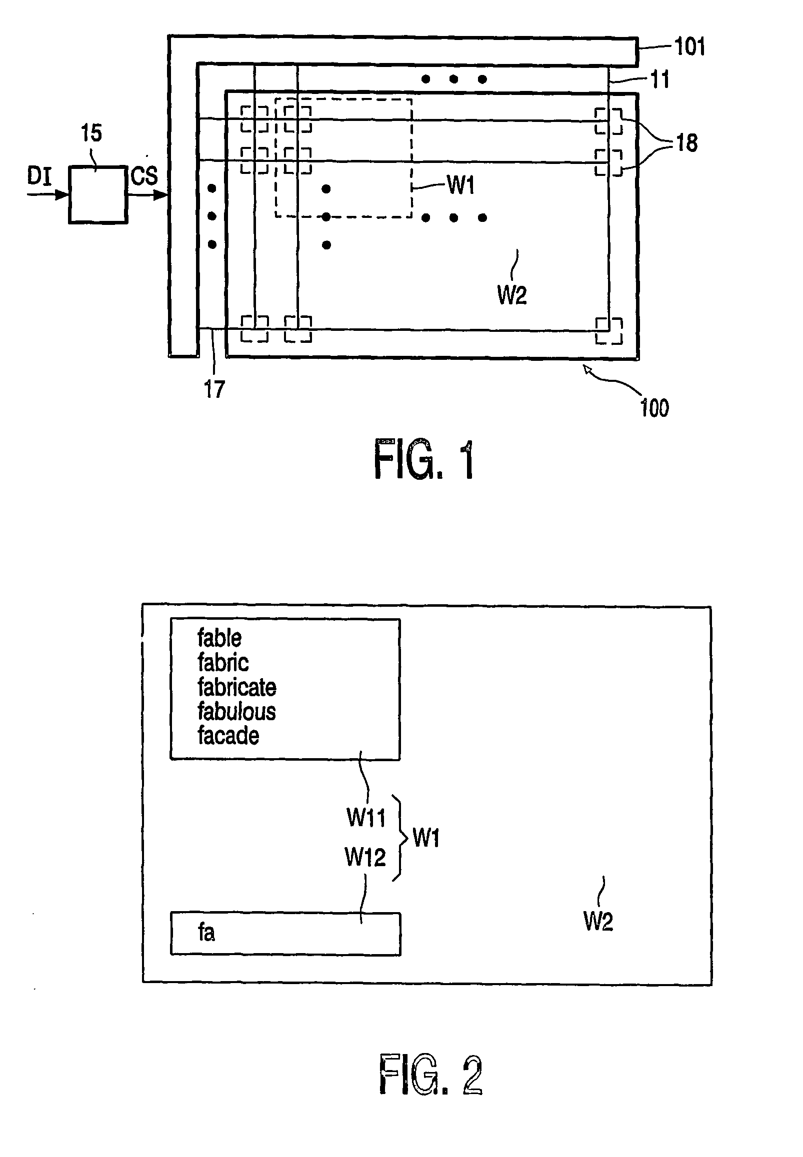
[0053]FIG. 1 shows schematically a display apparatus with a driver 101 and a bi-stable matrix display 100. The matrix display 100 comprises pixels 18 associated with intersections of the select electrodes 17 and data electrodes 11. Usually, the select electrodes 17 extend in the row direction and are also referred to as row electrodes and the data electrodes 11 extend in the column direction and are also referred to as column electrodes. Usually, the bi-stable matrix display 100 is an active matrix display which comprises transistors 19 (shown in FIG. 5, not shown in FIG. 1) which are controlled by select voltages on the select electrodes 17. A particular row of pixels 18 of which the control inputs are connected with a particular one of the select electrodes 17 is selected if the driver 101 (the select driver 16 of FIG. 5) supplies a select voltage to this particular one of the select electrodes 1...


PUM


Abstract

A bi-stable display (100) is driven by supplying (101) voltage waveforms to pixels (18) of the display (100). It is determined (150), based on information to be displayed (DI) on the display (100) during an image update period (IUP), which pixels (18) have to change their optical state during the image update period (IUP). A sub-area of pixels (WI) is determined (151) which has to be updated during this image update period (IUP). The dimensions of the sub-area (W1) are dynamically determined to cover the pixels (18) which have to change their optical state during this image update period (IUP). The drive circuit (101) is controlled (152) to only address the pixels (18) of the sub-area (WI).

Description

FIELD OF THE INVENTION [0001] The invention relates to a drive circuit for driving a bi-stable display device, to a display apparatus comprising a bi-stable display device and such a drive circuit, and to a method of driving a bi-stable display device. [0002] Bi-stable display devices, such as, for example, electrophoretic matrix displays are used in, for example, electronic books, mobile telephones, personal digital assistants, laptop computers, and monitors. BACKGROUND OF THE INVENTION [0003] An electrophoretic display device is known from international patent application WO 99 / 53373. This patent application discloses an electronic ink display which comprises two substrates, one of which is transparent, the other substrate is provided with electrodes arranged in rows and columns. Display elements or pixels are associated with intersections of the row and column electrodes. Each display element is coupled to the column electrode via a main electrode of a thin-film transistor (furth...

Claims


Application Information

Patent Timeline
IPC IPC(8): G09G3/34G02F1/167G09G3/20G09G3/36
CPCG02F1/167G09G3/2014G09G3/344G09G2300/08G09G2310/0205G09G2330/021G09G2310/04G09G2310/06G09G2310/061G09G2320/04G09G2310/0275
Inventor ZHOU, GUOFUJOHNSON, MARK THOMAS
Owner KONINKLIJKE PHILIPS ELECTRONICS NV
Why Eureka
Try Eureka