Imaging reader and method with internal window reflections directed away from imager

a reader and reflection technology, applied in the field of optical readers, can solve the problems of significant compromise of automatic exposure settings and reader performance, disadvantageous use of internal illuminator, and external mounting of illuminator, so as to enhance reader performance, enhance reader performance, and reliably capture an image of a target

Active Publication Date: 2007-08-23
SYMBOL TECH LLC
View PDF9 Cites 54 Cited by
  • Summary
  • Abstract
  • Description
  • Claims
  • Application Information

AI Technical Summary

Benefits of technology

[0016] Another object of this invention is to reliably capture an image of a target without creating hot spots that degrade the captured image.
[0017] Still another object of the present invention is to enhance reader performance by minimizing, if not eliminating, internal reflections at the window from reaching the imager.
[0018] Yet another object of the present invention is to provide more flexibility and options for the industrial design of an imaging reader.

Problems solved by technology

Although generally satisfactory for its intended purpose, the use of an internal illuminator is disadvantageous.
This reflected portion of the illumination light creates undesirable hot spots in the captured image of the symbol and may significantly compromise automatic exposure settings and reader performance.
However, the externally mounted illuminator is subject to breakage, especially if dropped or roughly handled, and is exposed to environmental hazards such as dust and like contaminants.
Also, the externally mounted illuminator is not located on the optical axis of the imager, thereby causing a parallax effect and non-uniform illumination at both near and far working distances from the reader.
In addition, when a target is placed very close to an imaging reader having an externally mounted illuminator, the center of the target is not well illuminated, if at all.
However, this technique limits the location of the window and constrains the overall design of the housing.
However, tilting the window, although acceptable in some applications, is not altogether desirable in other applications, for example, for an imaging reader, because the tilt angle required would be large, i.e., on the order of 45 degrees, which may be too large and difficult to implement in certain imaging readers and overly constrain the industrial design of the reader.

Method used


Image

  • Imaging reader and method with internal window reflections directed away from imager
  • Imaging reader and method with internal window reflections directed away from imager
  • Imaging reader and method with internal window reflections directed away from imager

Examples


Embodiment Construction

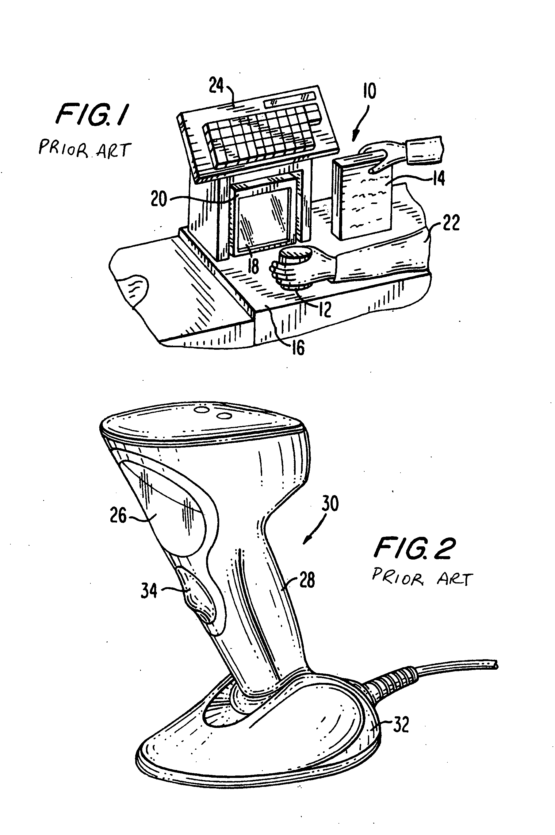
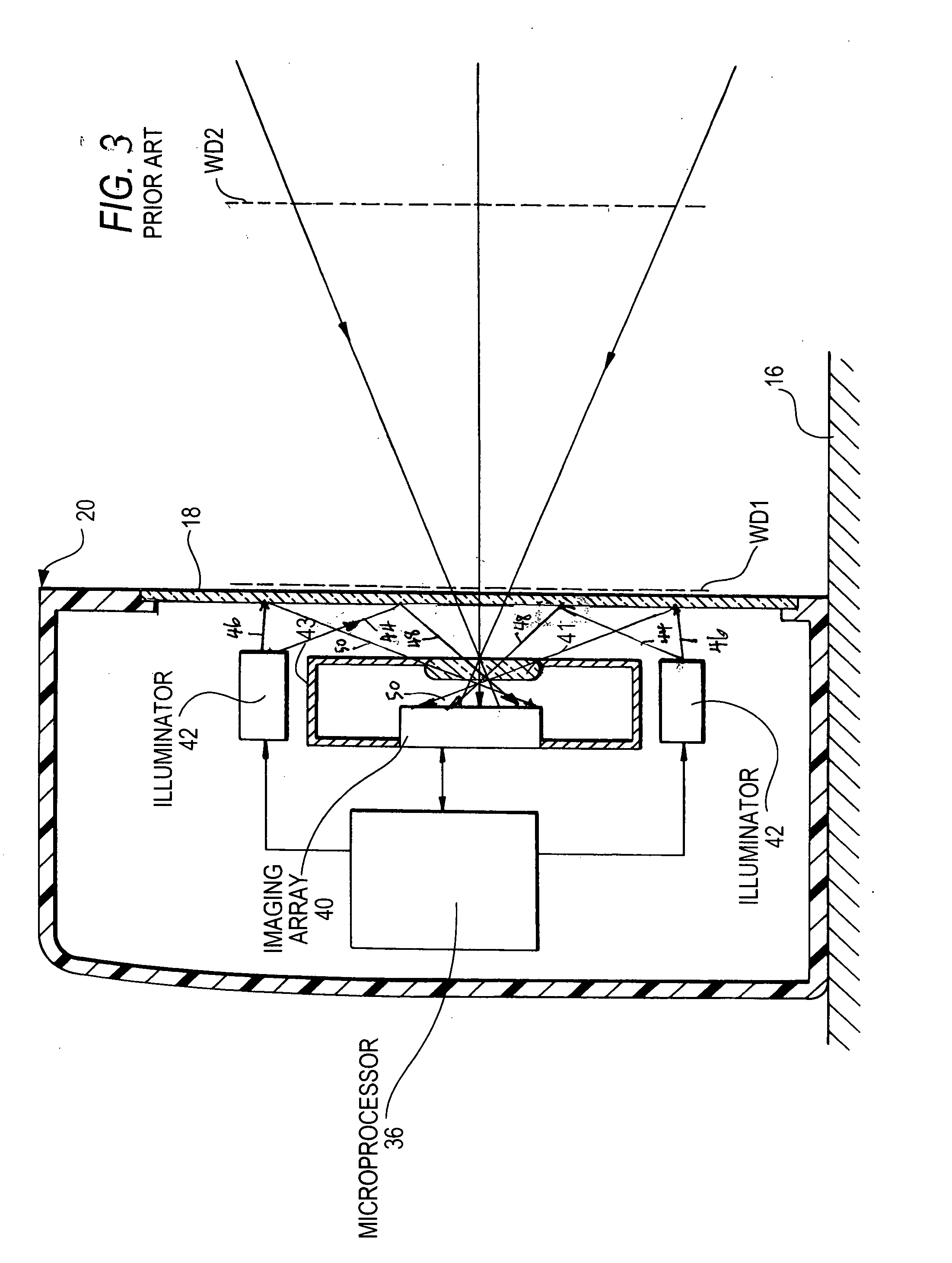
[0029] Reference numeral 10 in FIG. 1 generally identifies a workstation in accordance with the prior art for processing transactions and specifically a checkout counter at a retail site at which products, such as a can 12 or a box 14, each bearing a target symbol, are processed for purchase. The counter includes a countertop 16 across which the products are slid at a swipe speed past a vertical planar window 18 of a box-shaped housing of a vertical slot reader 20 mounted on the countertop 16. A checkout clerk or operator 22 is located at one side of the countertop, and the reader 20 is located at the opposite side. A cash / credit register 24 is located within easy reach of the operator.

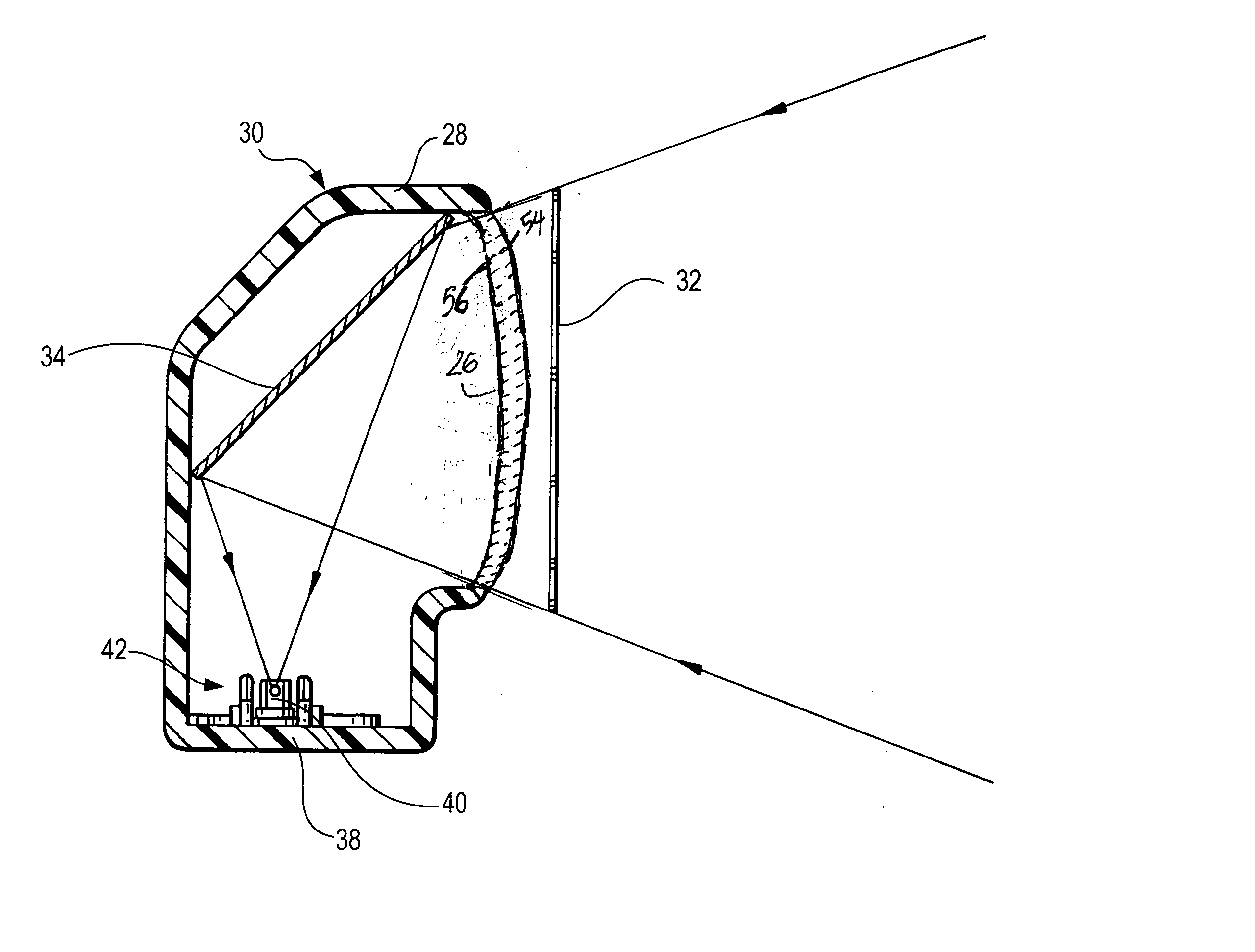
[0030] Reference numeral 30 in FIG. 2 generally identifies another reader having a different configuration from that of reader 20. Reader 30 also has a generally vertical planar window 26 and a gun-shaped housing 28 supported by a base 32 for supporting the reader 30 on a countertop. The reader 30 ca...


PUM


Abstract

A target is illuminated with illumination light for image capture by a solid-state imager of an imaging reader. Internal reflections of the illumination light at a window are minimized, if not eliminated, by configuring the window as a non-planar optical element operative for redirecting the internal reflections away from the imager to enhance reader performance.

Description

BACKGROUND OF THE INVENTION [0001] 1. Field of the Invention [0002] The present invention generally relates to an electro-optical reader for reading a target, especially one- and two-dimensional symbols, by using a solid-state imager for image capture and a target illuminator for directing illumination light to and through a window on the reader and, more particularly, to configuring the window to redirect the illumination light incident thereon from the illuminator and reflected from the window away from the imager to enhance reader performance. [0003] 2. Description of the Related Art [0004] Flat bed laser readers, also known as horizontal slot scanners, have been used to electro-optically read one-dimensional bar code symbols, particularly of the Universal Product Code (UPC) type, at a point-of-transaction workstation in supermarkets, warehouse clubs, department stores, and other kinds of retailers for many years. As exemplified by U.S. Pat. No. 5,059,779; U.S. Pat. No. 5,124,539...

Claims


Application Information

Patent Timeline
Patent Type & Authority Applications(United States)
IPC IPC(8): G06K7/10
CPCG06K7/10722
Inventor VINOGRADOV, IGORBARKAN, EDWARDDRYZMALA, MARK
Owner SYMBOL TECH LLC
Why Eureka
Try Eureka