
Dialysate mixing and dialyzer control for dialysis system

a dialyzer control and dialysis system technology, applied in the field of dialysis system, can solve the problems of demanding, restrictive and tiring schedule of patients, in-center patients having to follow uncompromising schedules, and feeling exhausted, so as to facilitate patient flexibility, ease patient burden, and improve treatment efficiency

Inactive Publication Date: 2013-03-07
OUTSET MEDICAL
View PDF6 Cites 49 Cited by
  • Summary
  • Abstract
  • Description
  • Claims
  • Application Information

AI Technical Summary

Benefits of technology

This patent is about improving the process of preparing and purifying fluids for dialysis to make it more efficient and patient-friendly. The patent describes devices for heating, purifying, and cooling water to make dialysate, as well as a conductivity sensor to monitor the levels of certain components in the dialysate. The system also includes a pressure transducer to alert the patient when the dialysate is ready for use. The patient can also control the flow rate of the dialysate, ensuring all the fluid is used during a shorter treatment period. Overall, these improvements make the dialysis process less burdensome and more flexible for patients.

Problems solved by technology

Many patients receive dialysis treatment at a dialysis center, which can place a demanding, restrictive and tiring schedule on a patient.
Moreover, in-center patients must follow an uncompromising schedule as a typical center treats three to five shifts of patients in the course of a day.
As a result, many people who dialyze three times a week complain of feeling exhausted for at least a few hours after a session.

Method used


Image

  • Dialysate mixing and dialyzer control for dialysis system
  • Dialysate mixing and dialyzer control for dialysis system
  • Dialysate mixing and dialyzer control for dialysis system

Examples


Embodiment Construction

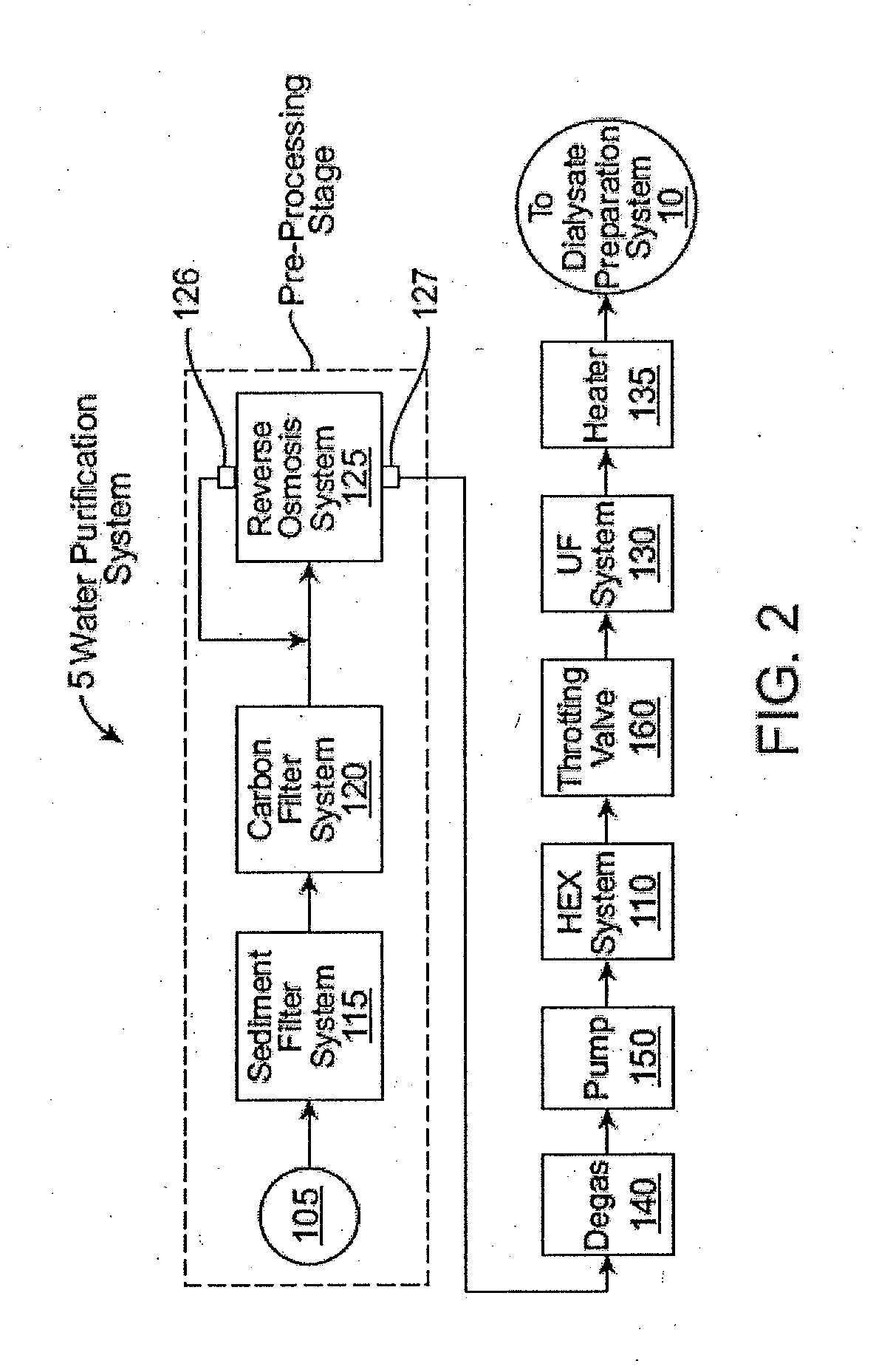
[0022]Disclosed herein are small, lightweight, portable, systems that have the capability of reliably, reproducibly, highly efficiently and relatively inexpensively providing a source of purified water of sufficient volumes for home dialysis. In addition, the systems disclosed herein require much less purified water at any one time than the volumes typically needed for dialysis today, thereby further reducing the expense of running the system at home. In addition, the systems described herein are capable of producing real-time, on-demand ultrapure water for dialysis, the gold standard of present-day dialysis. Disclosed herein are in-line, non-batch water purification systems that use a microfluidics heat exchanger for heating, purifying and cooling water. The systems described herein consume relatively low amounts of energy. The systems described herein although suitable for use in a home dialysis system, can be used in other environments where water purification is desired. The sys...


PUM

PropertyMeasurementUnit
timeaaaaaaaaaa
saturation pressureaaaaaaaaaa
temperatureaaaaaaaaaa

Abstract

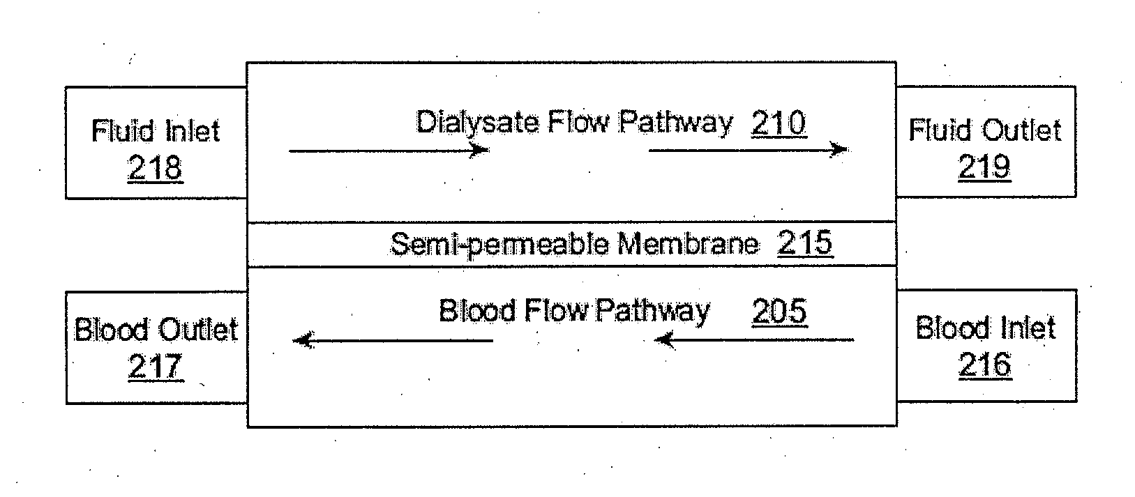
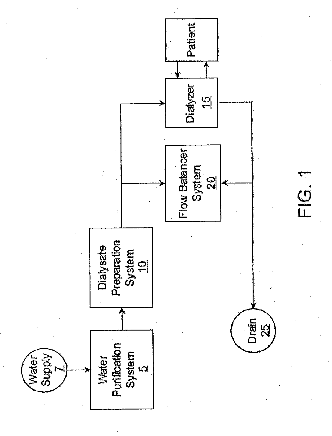
A medical dialysis system including a filtration system configured to filter a water stream, a water purification system configured to purify the water stream in a non-batch process, a mixing system, and a dialyzer system. The mixing system includes a supply of dialysate components, a conductivity sensor positioned within a fluid pathway through which the water stream flows, and a control mechanism having a pump configured to control an amount of the one or more dialysate components added to the water stream from the supply. The mixing system can produce a stream of dialysate from mixing the one or more dialysate components with the water stream in a non-batch process. The dialyzer system includes a dialyzer, a plurality of pumps capable of pumping the stream of dialysate across the dialyzer, and another conductivity sensor positioned downstream of the dialyzer within a fluid pathway through which the water stream flows.

Description

REFERENCE TO RELATED APPLICATIONS[0001]This application claims priority of U.S. Provisional Patent Application Ser. No. 61 / 529,157, filed on Aug. 30, 2011 and entitled DIALYSATE MIXING AND DIALYZER CONTROL FOR DIALYSIS SYSTEM. The disclosures of the Provisional patent application is hereby incorporated by reference in its entirety.[0002]This application is related to the following U.S. patent applications: (1) U.S. patent application Ser. No. 12 / 795,371, entitled “Microfluidic Devices” and filed Jun. 7, 2010, which claims priority to U.S. Provisional Patent Application Ser. No. 61 / 220,117, filed on Jun. 24, 2009; (2) U.S. patent application Ser. No. 12 / 795,498, entitled “Dialysis System With Ultrafiltration Control” and filed Jun. 7, 2010, which claims priority to U.S. Provisional Patent Application Ser. No. 61 / 267,043, filed on Dec. 5, 2009; (3) U.S. patent application Ser. No. 12 / 795,382, entitled “Fluid Purification System” and filed Jun. 7, 2010; and (4) U.S. patent application ...

Claims


Application Information

Patent Timeline
Patent Type & Authority Applications(United States)
IPC IPC(8): A61M1/16
CPCA61M1/1656A61M1/1605A61M1/1686A61M1/1662
Inventor CURTIS, JAMES R.
Owner OUTSET MEDICAL
Learn More