Driving A Display With A Polarity Inversion Pattern

a technology of polarity inversion and display panel, which is applied in the direction of television systems, signal generators with optical-mechanical scanning, instruments, etc., can solve the problems of inability to reach the final value within any addressing period, inability to display images in uniform colors, and inability to display moving images at the same time, so as to reduce the visibility of flicker caused by repeating light pulses, the effect of displaying moving images and high ra

Inactive Publication Date: 2008-04-24
KONINKLIJKE PHILIPS ELECTRONICS NV
View PDF9 Cites 32 Cited by
  • Summary
  • Abstract
  • Description
  • Claims
  • Application Information

AI Technical Summary

Benefits of technology

[0007]So, by increasing the refresh rate, a reduction of flicker has been achieved, while the non-uniformity caused by the incomplete charging of the pixels at this higher refresh rate has been reduced by an adapted polarity inversion scheme.
[0019]By varying the duration and / or the amplitude of the first and the second pulses in different ways in dependence on the brightness level to be delivered as described above, it is possible to further reduce artifacts, while allowing at the same time to exploit the maximum available light output of the light source.

Problems solved by technology

When doing this and applying a conventional polarity inversion scheme by inverting the polarity of the drive levels of a pixel for each subsequent display frame, a problem arises due to the incomplete charging of the display pixels.
So each frame period a large voltage swing is required, which means that the final value cannot be reached within any addressing period due to the incomplete charging of the pixel.
Moreover, each of the pixels may have slightly different parasitic parameters, resulting in a non-uniform image reproduction, because the pixels do not all reach a same value during the addressing period even when the voltage pulses have the same amplitude for all pixels.

Method used


Image

  • Driving A Display With A Polarity Inversion Pattern
  • Driving A Display With A Polarity Inversion Pattern
  • Driving A Display With A Polarity Inversion Pattern

Examples


first embodiment

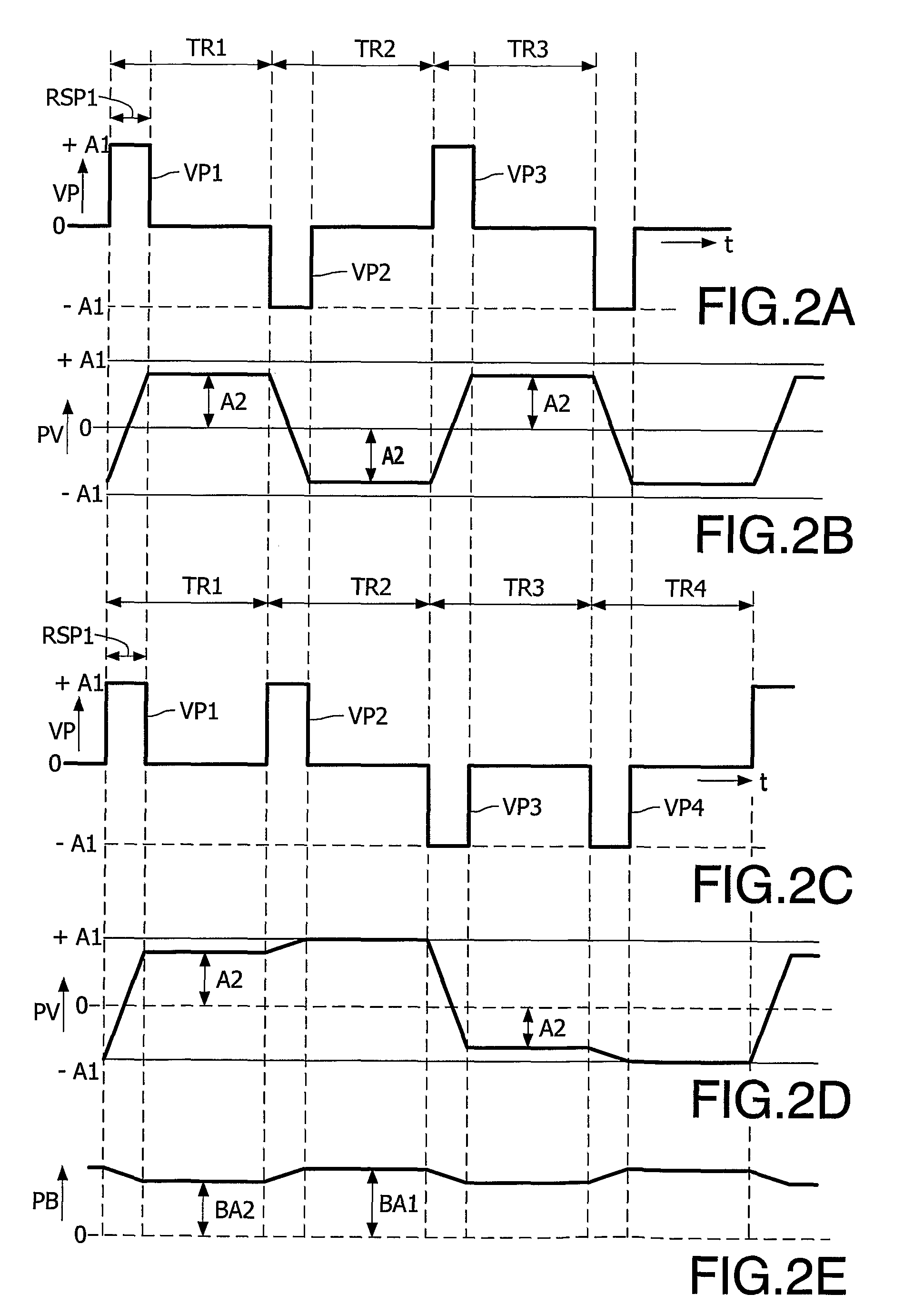
[0045]In order to overcome this non-uniformity problem, in the invention the polarity inversion scheme is adapted to drive a pixel of the display panel DP with an adapted drive signal being the drive signal V2 having a first polarity during a first group of refresh frame periods, and being the drive signal V2 with a reversed polarity during a subsequent second group of refresh frame periods, the first group and the second group each comprising at least two refresh frame periods.

[0046]An example of such a scheme is shown in FIGS. 2C to 2E. The voltages pulses VP as function of time t form the adapted drive signal that is obtained by applying this polarity inversion scheme to the drive signal V2. As shown in FIG. 2C, a first group of refresh frame periods is formed by refresh frame periods TR1 and TR2. During this first group of refresh frame periods, voltage pulses VP1 and VP2 with a positive amplitude A1 are driving the pixel P. During a second group of refresh frame period formed b...

second embodiment

[0061]FIGS. 3D to 3F show the invention which overcomes above described problem. The phase of the inversion scheme is shifted with respect to the de-interlace pattern. As can be seen in FIG. 3D, a first group of refresh frame periods comprises a first and a second refresh frame which include the voltage pulses VP1 and VP2 having a positive polarity. As the second refresh frame is selected a refresh frame, which is obtained by using data at least partially obtained by converting from an image frame which is different from the image frame of which the first refresh frame is obtained. In this embodiment the second voltage pulse VP2 is included in the second refresh frame. This second voltage pulse VP2 has an amplitude B1 different from the amplitude A1 of the first voltage pulse, as its amplitude B1 is obtained from an image frame which is different from the image frame from which the amplitude A1 of the first voltage pulse VP1 is obtained (see FIG. 3A).

[0062]The resulting pixel voltag...


PUM


Abstract

This invention relates to a method for driving a display panel (DP) having pixels (P). The display panel (DP) is driven with a sequence of image frames. The image frames are converted to a drive signal (V2) comprising refresh frames with a refresh frame period (TR) shorter than the image frame period. A pixel (P) of the display panel (DP) is driven with an adapted drive signal having a first polarity during a first group of refresh frame periods, and having a reversed polarity during a subsequent second group of refresh frame periods. The first group and the second group each comprise at least two refresh frame periods.

Description

FIELD OF INVENTION[0001]This invention relates to driving a display panel having pixels with a polarity inversion scheme.BACKGROUND OF INVENTION[0002]An active matrix device, such as described in U.S. Pat. No. 6,469,684, comprises an inversion circuitry coupled to drive signals, which inversion circuitry has at least one Cole sequence generator providing random, semi-random, or pseudo-random sequence patterns of the matrix. The Cole sequence generator provides a sequence of inversion patterns of pixel biasing over several frames. Over time each pixel is presented with a substantially equal number of positive and negative drive levels to prevent the generation of undesirable display artifacts, such as image retention or image sticking, that might occur under a direct current bias without inversion.[0003]Generally for television applications, this pixel biasing inversion is carried out once per frame, that is, with a frequency equal to a display refresh rate and synchronous with a vid...

Claims


Application Information

Patent Timeline
Patent Type & Authority Applications(United States)
IPC IPC(8): G06F3/038
CPCG09G3/3406G09G3/3614G09G3/3648G09G2310/0229G09G2320/064G09G2320/0247G09G2320/0261G09G2320/0276G09G2320/0633G09G2320/0204G02F1/133G09G3/20G09G3/36
Inventor STESSEN, JEROEN HUBERT CHRISTOFFEL JACOBUSSEVO, ALEKSANDAR
Owner KONINKLIJKE PHILIPS ELECTRONICS NV
Why Eureka
Try Eureka