Liquid crystal display device and display control method

A technology of liquid crystal display devices and liquid crystal panels, which is applied to static indicators, instruments, etc., can solve problems such as unstable phase relationship and image flickering, and achieve the effect of optimizing picture quality, improving picture quality, and eliminating picture flickering

Inactive Publication Date: 2012-10-17
HISENSE VISUAL TECH CO LTD
View PDF4 Cites 27 Cited by
  • Summary
  • Abstract
  • Description
  • Claims
  • Application Information

AI Technical Summary

Problems solved by technology

Since the image data sent to the LCD panel by the front end changes, the values ​​of Tv and TH also change with different images, so the phase relationship between STV and the display data of the first line of each frame image is not fixed, which means The phase relationship between the display data of the first line of each frame and the PWM controlling the backlight is not fixed, and combined with the influence of the frequency interference of Ffr and Fbl, it will cause the image to flicker

Method used


Image

  • Liquid crystal display device and display control method
  • Liquid crystal display device and display control method
  • Liquid crystal display device and display control method

Examples


Embodiment 1

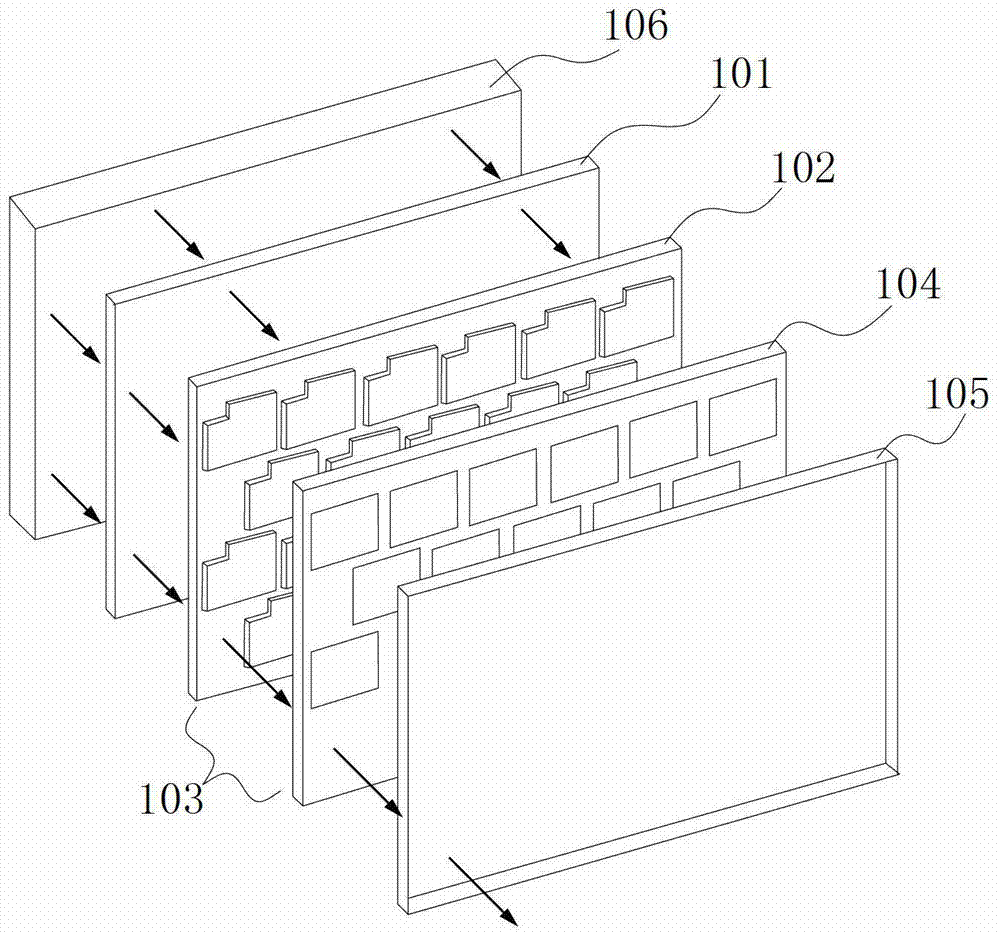
[0044] Such as Figure 4 As shown, this embodiment records a liquid crystal display device, including:

[0045] Liquid crystal panel circuit, including several thin film transistors;

[0046] A gate driving circuit for driving the gate of the liquid crystal panel circuit according to the received gate driving signal and controlling the switching of the gates of the plurality of thin film transistors; the gate driving signal includes a field synchronization signal;

[0047] A source drive circuit for outputting a corresponding gray-scale voltage to the liquid crystal panel circuit according to the received source drive signal;

[0048] The timing control circuit is used to output corresponding gate drive signals and source drive signals to the gate drive circuit and source drive circuit respectively according to the received motherboard control signals, and to output the backlight control signal to the backlight control circuit, so The backlight source control signal includes the field...

Embodiment 2

[0055] In addition to the content of the first embodiment, the frequency of the PWM signal generated by the backlight source control circuit is an integer multiple of the frequency of the field synchronization signal, so that the image quality of the liquid crystal display is more optimized.

Embodiment 3

[0057] In this embodiment, in addition to the content of Embodiment 1 or Embodiment 2, in order to reduce the problem of excessive instantaneous inrush current, the backlight source generates multiple PWM signals and adjusts the phase between the multiple PWMs so that The multiple PWM signals have a fixed phase difference.

[0058] Such as Figure 5 As shown, taking 4 PWM signals as an example, the 4 PWM signals are named PWM1~PWM4 respectively. In this embodiment, the phase difference of PWM1~PWM4 is set to be 90 degrees (obtained by dividing 360 degrees by the total number of channels). Since each PWM frequency is N times the frequency of the field synchronization signal STV, N is an integer, which is much higher than the frequency recognized by the human eye, so even though there is a phase difference between PWM1~PWM4, the human eye will not feel the change of the backlight brightness. Affect the subjective effect.


PUM


Abstract

The invention discloses a liquid crystal display device, which comprises a liquid crystal panel circuit, a gate driving circuit, a source driving circuit, a time sequence control circuit, a backlight and a backlight control circuit, wherein the time sequence control circuit is used for outputting a gate driving signal and a source driving signal to the gate driving circuit and the source driving circuit correspondingly and outputting a backlight control signal to the backlight control circuit; the gate driving signal comprises a field synchronizing signal; the backlight control signal comprises a field synchronizing signal; the backlight control circuit is used for generating pulse-width modulation (PWM) signals and outputting the PWM signals to the backlight; and phase differences between the PWM signals and the field synchronizing signal are fixed. The invention also provides a liquid crystal display control method. The method is characterized by comprising the field synchronizing signal for controlling the output of the time sequence control circuit and the PWM signals for controlling the output of the backlight control circuit, so that the phase differences between the field synchronizing signal output by the time sequence control circuit and the PWM signals are fixed. By the liquid crystal display device and the liquid crystal display control method, the shortcoming that the image in the liquid crystal display device glitters is effectively overcome, and the quality of a liquid crystal display product is improved.

Description

Technical field [0001] The present invention relates to the field of liquid crystal display technology, in particular to a liquid crystal display device and a display control method. Background technique [0002] The liquid crystal display device includes four parts: one is a liquid crystal panel, which is generally referred to as an LCD panel; the second is a timing control module; the third is a backlight module; the fourth is a backlight control module. among them: [0003] LCD panel composition structure such as figure 1 As shown, from the back light source 106 to the observation surface from bottom to top: lower polarizer 101—lower glass (TFT layer) 102—liquid crystal 103—upper glass (color filter layer) 104—upper polarizer 105 . Control the brightness and darkness of the pixels corresponding to the panel by controlling the switch of TFT (thin film transistor). A sub-pixel is controlled by a TFT. For example, a panel with a resolution of 1366*768, the number of corresponding...

Claims


Application Information

Patent Timeline
Patent Type & Authority Applications(China)
IPC IPC(8): G09G3/36
Inventor 房好强黄顺明徐爱臣
Owner HISENSE VISUAL TECH CO LTD
Why Eureka
Try Eureka