

Liquid crystal display
- Summary
- Abstract
- Description
- Claims
- Application Information
AI Technical Summary
Benefits of technology
Problems solved by technology
Method used
Image

Examples
first embodiment
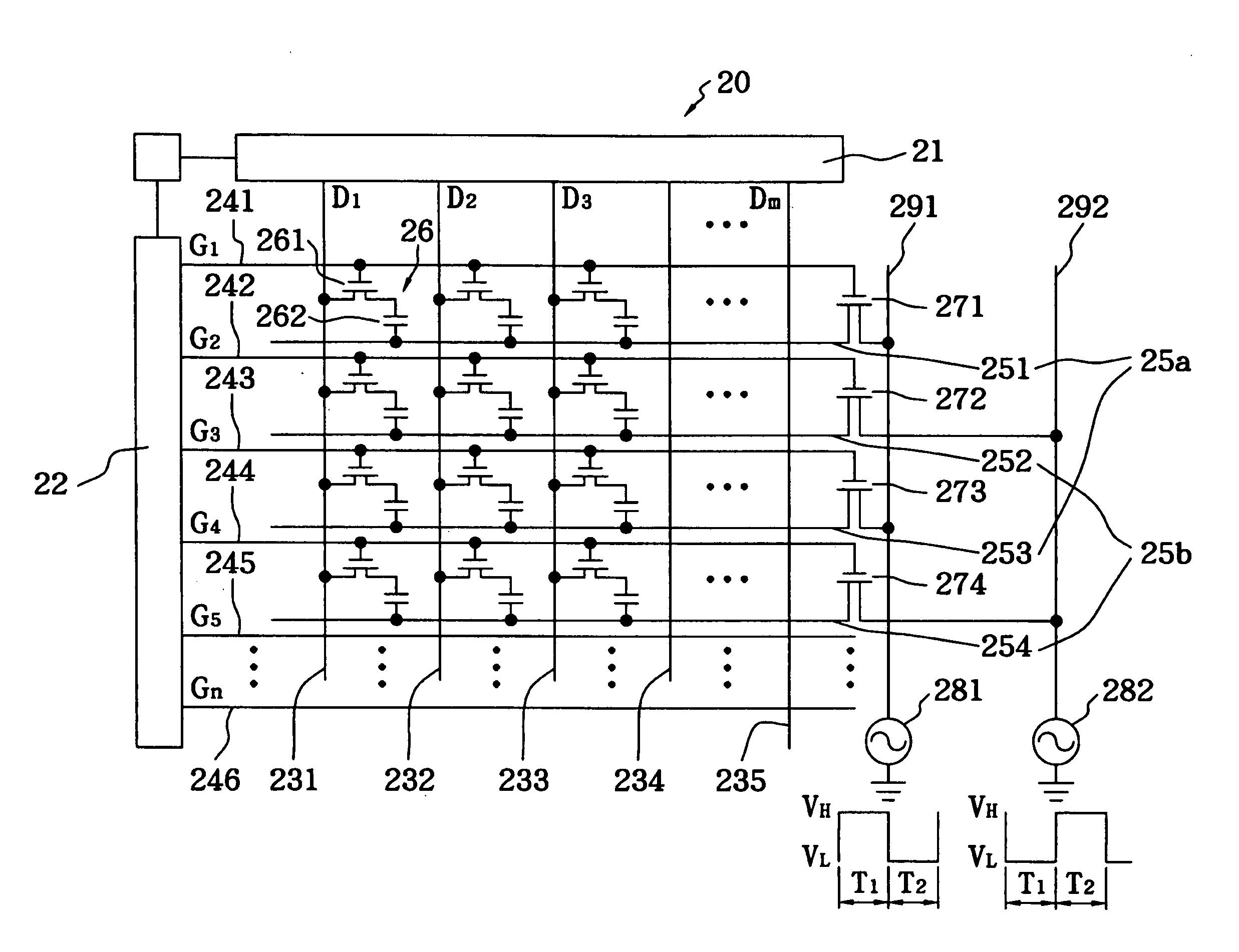
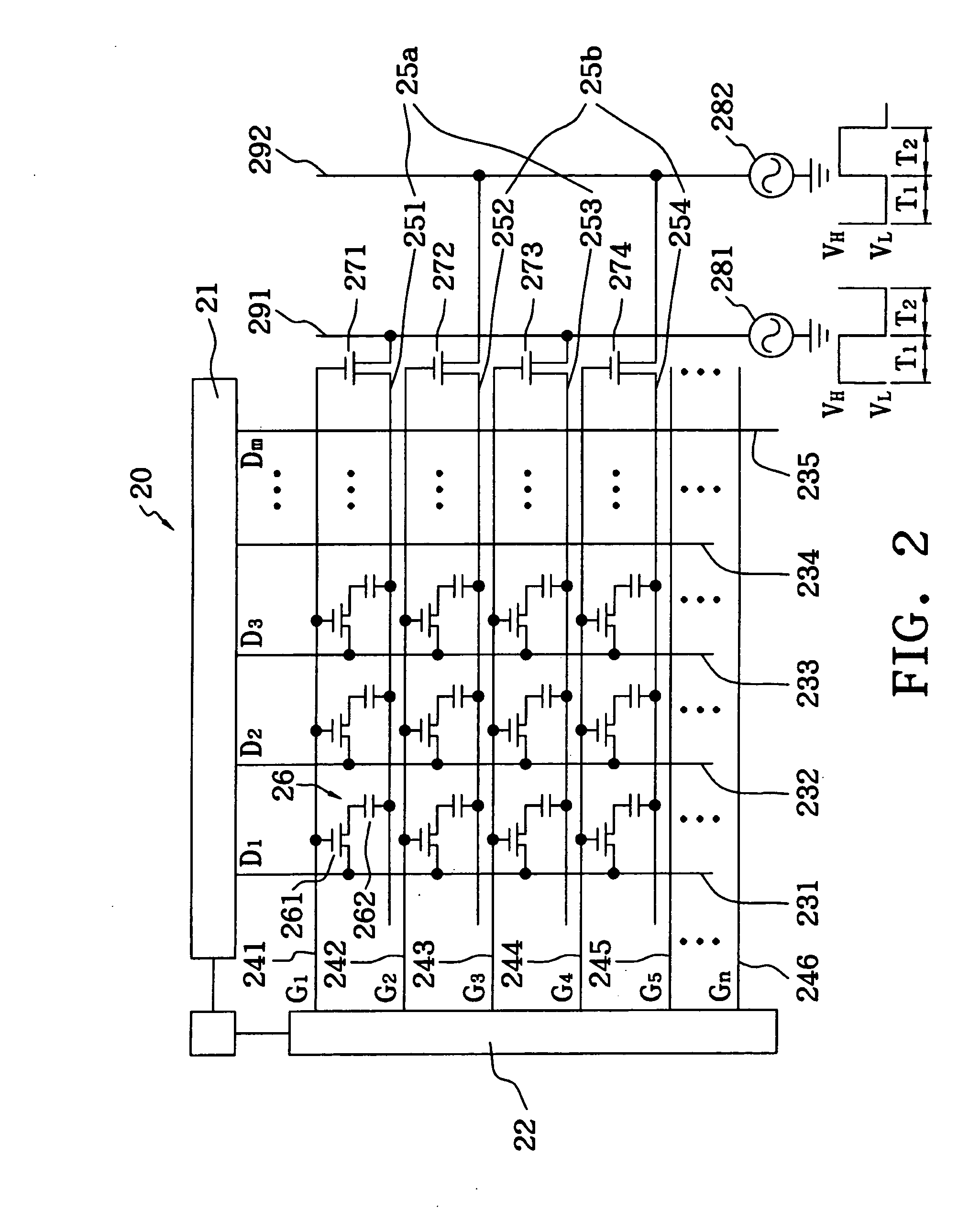
[0022] FIG. 2 is an equivalent circuit diagram of an LCD in accordance with the present invention. The LCD 20 has a plurality of pixels 26 formed by a plurality of parallel data lines (D1-Dm) 231-235 perpendicularly crossing a plurality of parallel scanning lines (G1-Gn) 241-246. Each of the pixels 26 further includes a thin film transistor (TFT) 261 and an LC capacitor 262 that controls the rotation directions of LC molecules. The data lines 231-235 transmit driving signals generated from a data driver module 21, and the scanning lines 241-246 transmit driving signals generating from a scanning driver module 22. When the gate electrode of the TFT 261 of the pixel 26 is selected by the scanning signals, the TFT (n channel) 261 is turned on and allows a data signal to write into a storage capacitor. In the LCD 20 as shown in FIG. 2, all the LC capacitors 262 electrically shorting to one of the scanning lines 241 are together electrically connected to a switch electrode 251, and their...
third embodiment
[0025] FIGS. 3(a) is an equivalent circuit diagram of an LCD in accordance with the present invention. The LCD 30 has a plurality of pixels 36 formed by a plurality of parallel data lines (D1-Dm) 331-335 perpendicularly crossing a plurality of parallel scanning lines (G1-Gn) 341-346. Each of the pixels 36 further includes a TFT 361 and an LC capacitor 362 that controls the rotation directions of LC molecules. The data lines 331-335 transmit driving signals generated from a data driver module 31, and the scanning lines 341-346 respectively transmit driving signals generated from a scanning driver module 32. In the LCD 30 as shown in FIG. 3, all the LC capacitors 362 electrically shorting to one of the scanning lines 341 are together electrically connected to a switch electrode 351, and their another terminals are respectively electrically shorts to their corresponding TFTs 361 of which gate electrodes are together electrically connected to the scanning lines 341. The other switch ele...
fourth embodiment
[0027] FIGS. 4 is an equivalent circuit diagram of an LCD in accordance with the present invention. The LCD 40 has a plurality of pixels 36 formed by a plurality of parallel data lines (D1-Dm) 431-435 perpendicularly crossing a plurality of parallel scanning lines (G1-Gn) 441-446. Each of the pixels 36 further includes a TFT 461 and an LC capacitor 462 that controls the rotational direction of the LC molecules. The data lines 431-435 transmit driving signals generated from a data driver module 41, and the scanning lines 441-446 respectively transmit driving signals generated from a scanning driver module 42. All the LC capacitors 462 electrically shorting to one of the scanning lines 441 are together electrically connected to a switch electrode 451, and their another terminals are respectively electrically shorts to their corresponding TFTs 461 of which gate electrodes are together electrically connected to the scanning lines 441. The other switch electrodes 452-454 are separately c...
PUM
 Abstract
Description
Claims
Application Information