Novel self-adaptive optical method and system of wavefront-free sensor

A technology of adaptive optics and wavefront sensors, applied in the field of optical communication, can solve the problems that the response speed cannot meet the fast requirements of the space optical communication system, the coupling energy attenuation effect is not obvious, and the high-order distortion cannot be compensated, etc., so as to eliminate Signal flicker effect, light weight, eliminate the effect of signal flicker

Inactive Publication Date: 2011-02-09
HUAZHONG UNIV OF SCI & TECH
View PDF4 Cites 20 Cited by
  • Summary
  • Abstract
  • Description
  • Claims
  • Application Information

AI Technical Summary

Problems solved by technology

In the application of some imaging systems, AO often only considers the turbulence in the inertial region for simplicity, and the turbulence scale ranges from several millimeters to tens of millimeters. In the long-distance space optical communication link, the beam divergence angle (such as Laser) the beam expansion area can reach the order of meters. At this time, it is difficult to achieve all-weather communication only considering the inertial area! The limitations of the turbulent atmospheric model used and the backward algorithm of the control loop are the key reasons why conventional AO is not suitable for application to free-space optical communication systems! For example, due to the rapid changes in atmospheric wind speed and turbulence intensity, the wavefront compensation effect obtained by the conventional AO fixed gain compensation algorithm is far from ideal
In 2007, B.L.ELLerbroek, J.S.Gibson and Y.T.Liu et al. studied the adaptive wavefront reconstruction algorithm based on the recursive least squares (RLS) optimized reconstruction matrix. In this algorithm, although the adaptive control loop replaces the classic AO system The feedback loop has achieved good results when the model error and sensor noise are large, but the real-time performance is still not ideal, and the response speed still cannot meet the fast requirements of the space optical communication system.
[0008] The wavefront detection performance of the wavefront sensor is greatly reduced under strong turbulence, and because the conventional AO system implements wavefront compensation on the aperture plane, the high-order distortion cannot be compensated. Therefore, in the long-distance high-speed free-space optical communication system, The effect of conventional AO on improving the coupling energy attenuation caused by turbulent atmosphere is not obvious
[0009] The conventional AO system adopts closed-loop control, which is large in size, complex in algorithm and slow in response

Method used


Image

  • Novel self-adaptive optical method and system of wavefront-free sensor
  • Novel self-adaptive optical method and system of wavefront-free sensor

Examples


Embodiment 1

[0060] Example 1. A Novel Adaptive Optics Approach Without a Wavefront Sensor

[0061] The method includes the following steps:

[0062] a. Use statistical predictive analysis methods to establish an initial wavefront.

[0063] This is the key to the technology of the present invention. According to the characteristics of atmospheric turbulence, various turbulence models are statistically analyzed to establish an adaptively adjustable initial wave front as a reference wave front for correcting the distorted wave front. The method is to perform variational processing on the refractive index structure functions of various turbulence models, use the multi-layer turbulence atmospheric model, and then use the Zernik wave front model to statistically analyze the initial wave front in the circular domain.

[0064] The initial wavefront is used as the reference wavefront for wavefront correction. In the subsequent wavefront reconstruction genetic algorithm, adaptive adjustment will b...

Embodiment 2

[0075] Example 2. Novel adaptive optics system without wavefront sensor

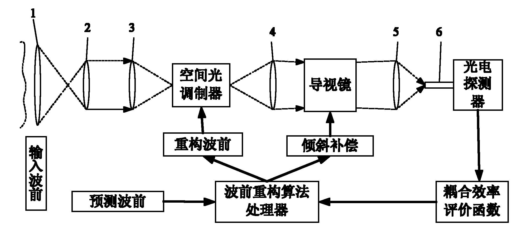
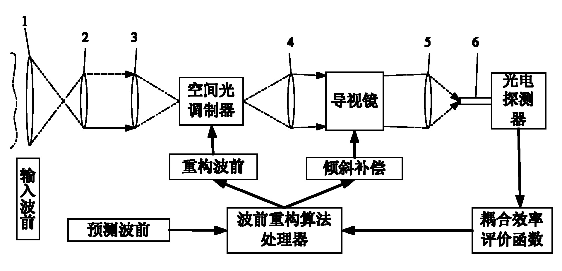
[0076] The structure of the novel adaptive optics system without wavefront sensor is as follows figure 1 As shown: the system is mainly composed of an optical receiving aperture lens 1, a beam collimating lens 2, a first converging lens 3, a spatial light modulator, a collimating lens 4, a guide mirror, a second converging lens 5 and a photodetector 6 , they are in turn connected by optical path signals.

[0077] The invention provides the above-mentioned novel adaptive optics system without a wavefront sensor, and its application in high-speed space optical communication or optical imaging.

[0078] The specific application process of the novel adaptive optics system without wavefront sensor of the present invention is as follows:

[0079] The first step, beam convergence and shaping:

[0080] The optical receiving aperture lens 1 of the receiver converges the light beam from the transmitter end of t...


PUM


Abstract

The invention provides a novel self-adaptive optical method and a system of a wavefront-free sensor. The method comprises the following steps of: establishing a initial wavefront; constructing a coupling efficiency evaluation function; acquiring a tilt compensation signal; and reconstructing wavefront matrix information; determining the optimal position of a guide endoscope; and adjusting a reconstructed wavefront matrix and the tilt compensation signal by a control loop. The system mainly comprises an optical receiving aperture lens (1), a light beam collimation lens (2), a first converging lens (3), a spatial light modulator, a collimation lens (4), the guide endoscope, a second converging lens (5) and a photodetector (6) which are sequentially connected by an optical path signal. The system is applied to high-speed spatial optical communication or optical imaging. The invention improves the reliability of a communication system, accords with the characteristics of the free spatial optimal communication system, has strong practicability and is convenient to popularize and apply.

Description

technical field [0001] The invention relates to the optical field wavefront distortion compensation system technology in the field of optical communication technology and adaptive optics technology, in particular to a novel adaptive optics method and system without a wavefront sensor. Background technique [0002] With the increasing amount of spatial data information, the demand for data transmission bandwidth is also increasing. The bandwidth advantage of space optical communication will make it the main technical solution for space science research, inter-satellite communication, satellite-ground communication, manned spaceflight, lunar exploration project and earth observation data transmission and exchange. The United States, France, Russia, Japan and other developed countries, as well as the European Community, included satellite payload technology in the space optical communication test plan as early as the 1970s, and carried out communication tests. Since then, spac...

Claims


Application Information

Patent Timeline
Patent Type & Authority Applications(China)
IPC IPC(8): H04B10/10G02B27/00G02B26/06H04B10/11
Inventor 元秀华
Owner HUAZHONG UNIV OF SCI & TECH
Why Eureka
Try Eureka