
Wireless charging receiving module and wireless charging system

A wireless charging and receiving module technology, applied in battery circuit devices, current collectors, electric vehicles, etc., can solve the problems of limited charging location and limited wireless charging distance.

Inactive Publication Date: 2018-07-06
联永智能科技(上海)有限公司
View PDF2 Cites 4 Cited by
  • Summary
  • Abstract
  • Description
  • Claims
  • Application Information

AI Technical Summary

Problems solved by technology

[0005] The invention provides a wireless charging receiving module and a wireless charging system to solve the problems of limited wireless charging distance and limited charging position of existing wearable devices

Method used


Image

  • Wireless charging receiving module and wireless charging system
  • Wireless charging receiving module and wireless charging system
  • Wireless charging receiving module and wireless charging system

Examples


Embodiment Construction

[0017] The present invention will be further described in detail below in conjunction with the accompanying drawings and embodiments. It should be understood that the specific embodiments described here are only used to explain the present invention, but not to limit the present invention. In addition, it should be noted that, for the convenience of description, only some structures related to the present invention are shown in the drawings but not all structures.

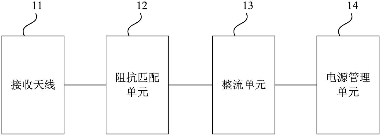
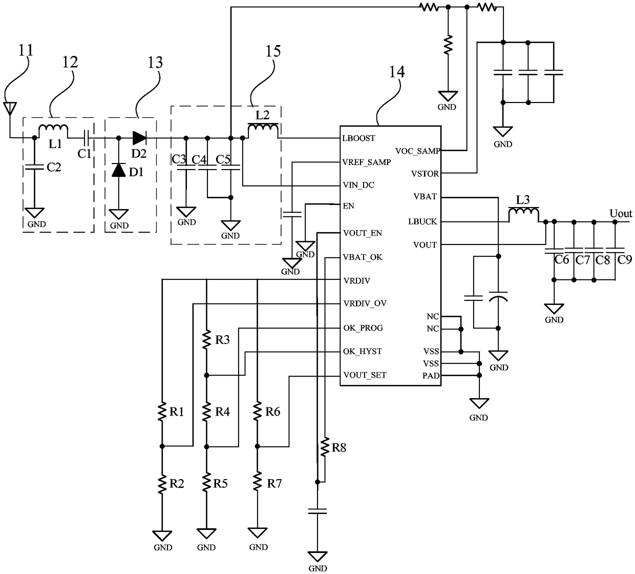
[0018] An embodiment of the present invention provides a wireless charging receiving module, refer to figure 1 , figure 1 It is a schematic structural diagram of a wireless charging receiving module provided by an embodiment of the present invention. The wireless charging receiving module includes: a receiving antenna 11, an impedance matching unit 12, a rectifying unit 13, and a power management unit 14;

[0019] The receiving antenna 11 is used to receive electromagnetic wave signals;

[0020] The impedance ma...


PUM


Abstract

The embodiment of the invention discloses a wireless charging receiving module and a wireless charging system. The wireless charging receiving module comprises a receiving antenna, an impedance matching unit, a rectifying unit and a power management unit. The receiving antenna is used for receiving electromagnetic wave signals. The impedance matching unit is electrically connected with the receiving antenna and used for carrying out impedance matching to make the electromagnetic wave signals transmitted at the maximum power. The rectifying unit is electrically connected with the impedance matching unit and used for converting the electromagnetic wave signals into DC signals. The power management unit is electrically connected with the rectifying unit and used for amplifying the DC signalsfor loads. By means of the technical scheme, the problems that an existing wearable device is limited in wireless charging distance and the charging position is limited can be solved.

Description

technical field [0001] Embodiments of the present invention relate to the technical field of wireless charging, and in particular to a wireless charging receiving module and a wireless charging system. Background technique [0002] Existing wearable devices are favored by more and more users because of their powerful functions. For wearable devices, the biggest challenge is how to properly and conveniently supply them with continuous power, and for many current wristband and watch designs, users must first take them off and plug them into wired chargers. Charging, charging is more troublesome. [0003] In order to solve the above problems, many products adopt an electromagnetic induction charging scheme. This solution utilizes resonant coils to conduct electrical energy. Specifically, a sending coil is set in the charger, and a receiving coil is set on the wearable device. By applying a changing current to the sending coil to generate a change in the electromagnetic field...

Claims


Application Information

Patent Timeline
Patent Type & Authority Applications(China)
IPC IPC(8): H02J50/20H02J7/00
Inventor 杨光轩北松
Owner 联永智能科技(上海)有限公司
Learn More