A cross-well electromagnetic logging signal transmitting electronic system

A signal transmission and electronic system technology, which is applied in wellbore/well components, construction, earthwork drilling and production, etc., can solve the problems of low logging accuracy, small logging distance, low emission energy, etc., and achieve impedance matching, The effect of increased strength and increased lateral detection depth

Active Publication Date: 2017-06-16
HUAZHONG UNIV OF SCI & TECH
View PDF6 Cites 1 Cited by
  • Summary
  • Abstract
  • Description
  • Claims
  • Application Information

AI Technical Summary

Problems solved by technology

However, the emission energy of the emission electronic system of the existing domestic logging system is not high, resulting in low logging accuracy and a small logging distance

Method used


Image

  • A cross-well electromagnetic logging signal transmitting electronic system
  • A cross-well electromagnetic logging signal transmitting electronic system
  • A cross-well electromagnetic logging signal transmitting electronic system

Examples


Embodiment Construction

[0021] In order to make the object, technical solution and advantages of the present invention clearer, the present invention will be further described in detail below in conjunction with the accompanying drawings and embodiments. It should be understood that the specific embodiments described here are only used to explain the present invention, not to limit the present invention. In addition, the technical features involved in the various embodiments of the present invention described below can be combined with each other as long as they do not constitute a conflict with each other.

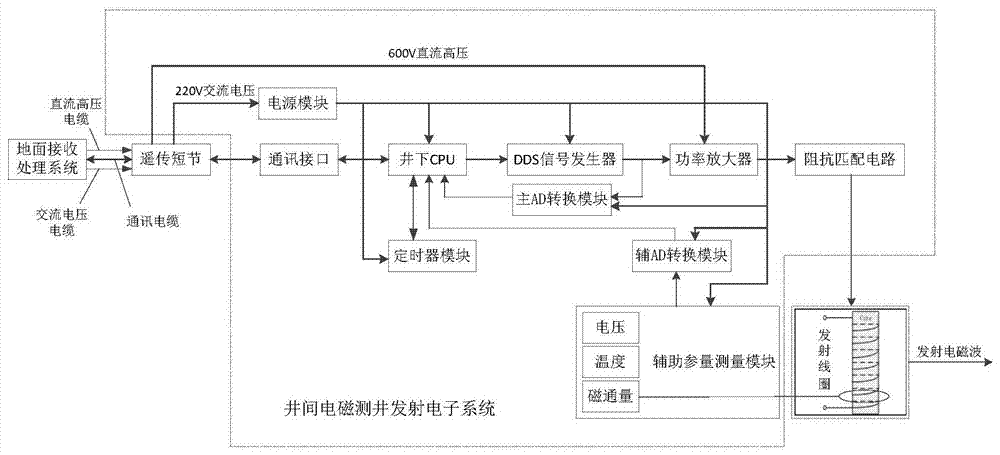
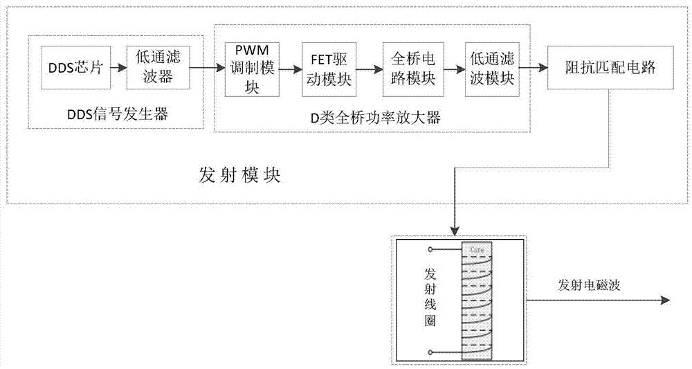
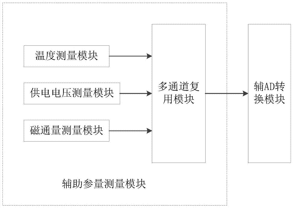
[0022] figure 1 Shown is a schematic structural diagram of the transmitting electronic system of the present invention, including: power supply module, downhole CPU, timer module, DDS signal generator, power amplifier, impedance matching circuit, auxiliary parameter measurement module, and main and auxiliary AD conversion modules.

[0023] The 220V AC voltage and 600V DC high voltage of the gro...


PUM


Abstract

The invention discloses a cross-well electromagnetic well logging signal emission electronic system and belongs to the technical field of cross-well electromagnetic well logging. A power amplification circuit is adopted to perform power amplification on excitation signals, the power amplification circuit adopts high-pressure power supply, and high-energy low-frequency electromagnetic waves are generated; the emission electronic system is provided with a precise timer module which is used for recording the accurate time of an emission signal and calculating phases of the emission signal and a receiving signal in a receiving well. The emission electronic system is formed by a power module, an underground CPU (Central Processing Unit), a timer module, a DDS (Direct Digital Synthesizer) signal generator, a power amplifier, an impedance matching circuit, an auxiliary parameter measuring module, a main AD (Analog Digital) conversion module and an auxiliary AD conversion module. The cross-well electromagnetic well logging signal emission electronic system can generate high-energy electronic waves, and during electromagnetic well logging, cross-well stratum resistivity is calculated combining the emission data and receiving data and accordingly the cross-well oil and gas distribution is obtained through inversion.

Description

technical field [0001] The invention belongs to the technical field of cross-well electromagnetic logging, and more specifically relates to a cross-well electromagnetic logging signal transmitting electronic system, which is used for emitting high-energy electromagnetic waves. Background technique [0002] Although conventional wireline logging has high resolution, its detection depth can only reach a range of a few meters, while geophysical prospecting has a deep detection depth, but its resolution is poor, and it cannot make fine evaluation of reservoirs. At the same time, during the development period, oilfields need to track and monitor the dynamics of reservoir injection-production profiles, evaluate the distribution of remaining oil, and find oil and gas-rich areas to meet the needs of secondary development and monitoring of injection-production profiles in the oilfield, thereby improving the drilling success rate and ultimate recovery rate. [0003] The interwell elec...

Claims


Application Information

Patent Timeline
Patent Type & Authority Patents(China)
IPC IPC(8): E21B49/00E21B47/13
CPCE21B47/13E21B49/00
Inventor 周凯波段燕云曾玲曹攀辉
Owner HUAZHONG UNIV OF SCI & TECH
Why Eureka
Try Eureka