Control method of controlling six-horizon sliding sleeve through three pipelines

A control method and sliding sleeve technology, applied in earthwork drilling, wellbore/well valve devices, wellbore/well components, etc., can solve problems such as affecting recovery rate, poor process applicability, and large interlayer pressure conflicts , to achieve the effects of improving recovery efficiency, strong applicability, and small resistance loss

Active Publication Date: 2020-09-15
CHINA NAT OFFSHORE OIL CORP +1
View PDF7 Cites 5 Cited by
  • Summary
  • Abstract
  • Description
  • Claims
  • Application Information

AI Technical Summary

Problems solved by technology

The current problem of multi-layer separate mining is that there are many layers, and the pressure contradiction between layers is large. Simultaneous multi-layer mining will cause serious breakthrough in some layers, which will affect the overall recovery rate.
At present, the focus of foreign research on multi-layer separate injection and separate mining is the use of hydraulic control technology. This technology takes advantage of the advantages of good stability and reliability of hydraulic control sliding sleeves. However, the technical problem of hydraulic control technology is that each layer The hydraulic control sliding sleeve needs two hydraulic control pipelines for control. When the number of layers is large, it will lead to too many hydraulic control pipelines, resulting in poor process applicability

Method used


Image

  • Control method of controlling six-horizon sliding sleeve through three pipelines
  • Control method of controlling six-horizon sliding sleeve through three pipelines
  • Control method of controlling six-horizon sliding sleeve through three pipelines

Examples


Embodiment 1

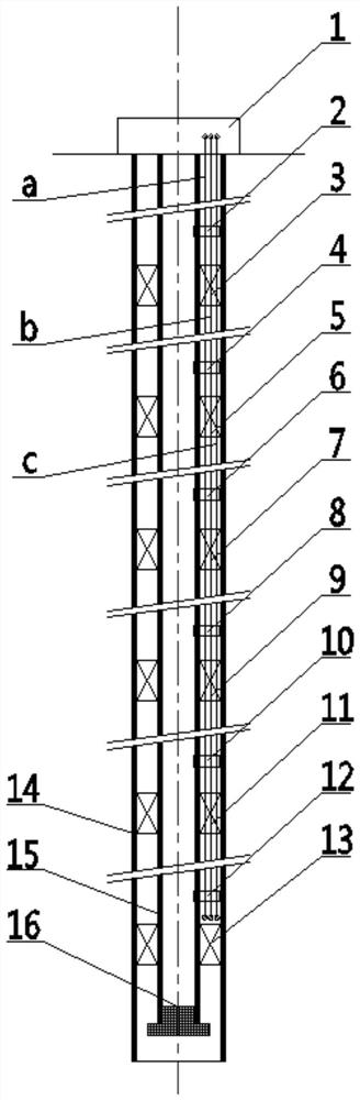
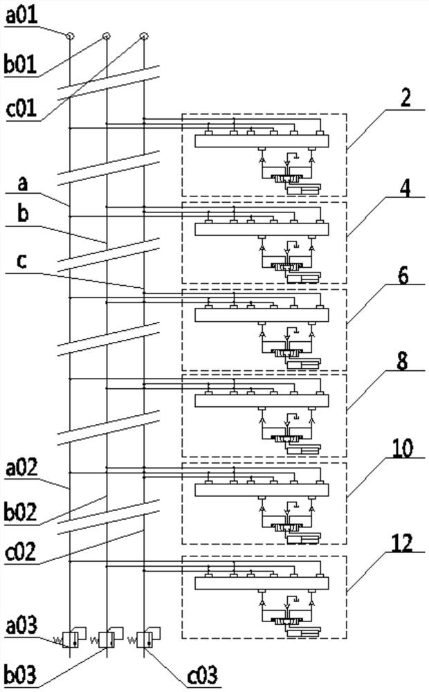
[0035] Such as figure 1 As shown, a downhole hydraulic system with three pipelines controlling six-layer sliding sleeves includes surface hydraulic control equipment (1), downhole hydraulic control system 1 (2), packer 1 (3), and downhole hydraulic control system 2 ( 4), packer 2(5), downhole hydraulic control system 3(6), packer 3(7), downhole hydraulic control system 4(8), packer 4(9), downhole hydraulic control system 5 (10), packer 5 (11), downhole hydraulic control system 6 (12), packer 6 (13), casing (14), tubing (15), tubing plug (16), hydraulic pipeline 1 (a), hydraulic line 2(b), hydraulic line 3(c).

[0036] Wherein, the ground hydraulic control equipment (1) is located on the ground and is used for suspending the casing (14) and the oil pipe (15), and providing hydraulic power for the hydraulic pipeline;

[0037] The hydraulic pipeline 1(a), hydraulic pipeline 2(b) and hydraulic pipeline 3(c) are interposed in the wellbore annulus of the casing (14) and tubing (15...

Embodiment 2

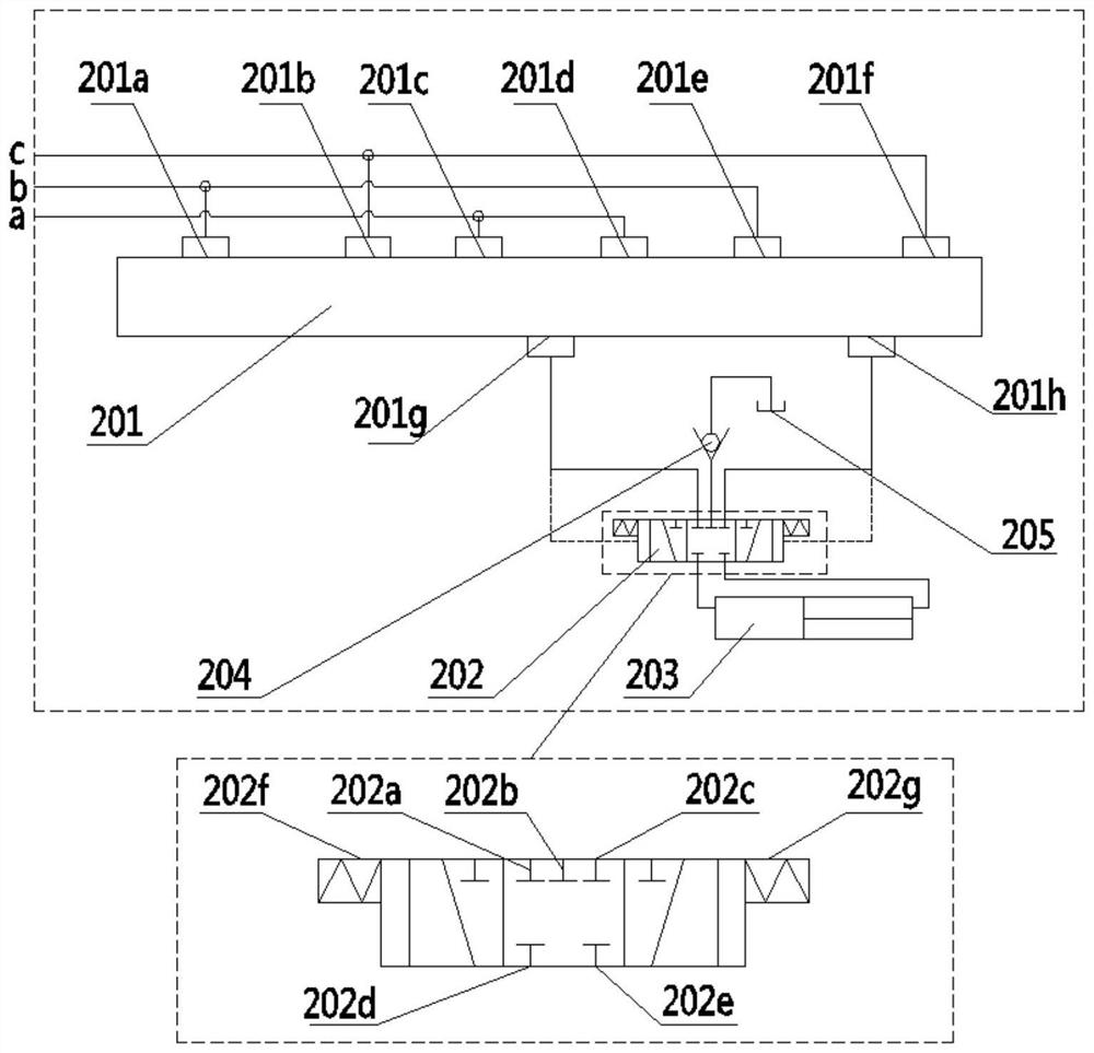
[0045] See attached Figure 10-14 , and specifically introduce the structure of the decoder itself. The structure of the 6 decoders is the same, specifically, the decoder includes the upper joint (A1), the upper valve body (A2), the valve control lock sleeve (A3), the valve control lock ball (A4), the upper return spring ( A5), upper spool (A6), sealing washer (A7), lower valve body (A8), lower spool (A9), lower return spring (A10) and lower joint (A11).

[0046] The upper valve body (A2) and the lower valve body (A8) form the whole valve body through threaded butt joint, and the upper joint (A1) is sealed with the outer port of the upper valve body (A2) through threaded connection, and the lower joint (A11 ) and the outer port of the lower valve body (A8) are sealed by threaded connection.

[0047]Between the upper joint (A1) and the upper valve body (A2) there is a first installation cavity for installing the valve control lock sleeve (A3) (the upper joint has a reduced di...


PUM


Abstract

The invention discloses a control method of controlling a six-horizon sliding sleeve through three pipelines. The control method comprises the following steps: sequentially connecting three hydraulicpipelines with ground hydraulic control equipment and six downhole hydraulic control systems from a ground hydraulic station to the downhole direction, wherein each downhole hydraulic control system corresponds to a to-be-exploited reservoir, and one packer is arranged under each downhole hydraulic control system to separate a shaft inner annular space to enable each horizon to form an independentspace; and controlling the oil pressure of the three hydraulic pipelines to separately control the opening state of each of decoders in the six downhole hydraulic control systems, and when the decoder in the target downhole hydraulic control system is opened, according to the control requirement of the moving direction of the sliding sleeve to be controlled, controlling the corresponding hydraulic pipeline to increase the oil pressure provided for the decoder to the operating pressure demanded by the sliding sleeve, so that a passage among the decoder, a decompression valve, the sliding sleeve, a one-way valve and an oil pipe opening hole of the this-horizon donwhole hydraulic control system is conducted to push the sliding sleeve to move so as to realize downhole hierarchical control.

Description

technical field [0001] The invention belongs to the technical field of oil and gas exploitation, and in particular relates to a method for controlling a six-layer sliding sleeve with three pipelines. Background technique [0002] Drilling in offshore oilfields is expensive and risky. Using one well for multi-layer commingled production is an effective way to increase recovery and reduce operating costs. Currently, the number of conventional injection-production wells is generally within 6 layers. The current problem of multi-layer separate mining is that there are many layers, and the pressure contradiction between layers is large. Simultaneous multi-layer mining will cause serious breakthrough in some layers, thus affecting the overall recovery rate. Therefore, it is necessary to effectively switch and control the opening of the separate injection and separate production layers, so as to achieve the purpose of adjusting the contradiction between layers and improving the rec...

Claims


Application Information

Patent Timeline
Patent Type & Authority Applications(China)
IPC IPC(8): E21B34/14E21B34/10E21B33/122E21B41/00E21B47/00
CPCE21B34/14E21B34/10E21B33/122E21B41/00E21B47/00
Inventor 薛德栋张玺亮张凤辉杨万有黄小凤沙吉乐
Owner CHINA NAT OFFSHORE OIL CORP
Why Eureka
Try Eureka