
A multi-block safety tire pressure balance method

A technology for air pressure balance and safety tires, applied in the field of transportation, can solve the problems of unbalanced and stable tire pressure, and achieve the effect of avoiding the reduction of the air in the tire and increasing the air tightness.

Active Publication Date: 2019-12-10
湖南邦链智能科技有限公司
View PDF7 Cites 0 Cited by
  • Summary
  • Abstract
  • Description
  • Claims
  • Application Information

AI Technical Summary

Problems solved by technology

[0004] Aiming at the defects in the prior art, the present invention provides a multi-block safety tire pressure balancing method, which is used to solve the problem that the tire pressure of each inflation layer cannot be balanced and stable during the tire inflation and use process

Method used


Image

  • A multi-block safety tire pressure balance method
  • A multi-block safety tire pressure balance method

Examples


Embodiment 1

[0029] This embodiment provides a multi-block safe tire air pressure balancing method, including the following steps:

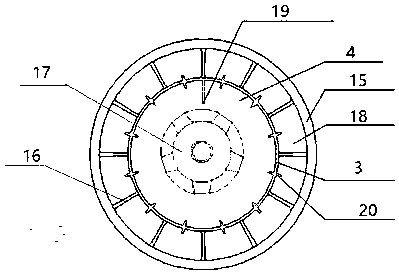
[0030] In the first step, the airbag layer 16 and the hollow layer 4 are arranged on the tire; the airbag layer 16 is arranged on the outer ring of the tire and is composed of a plurality of independent small airbags 18;

[0031] The airbag layer in the first step includes a plurality of small airbags of different shapes and sizes. .

[0032] In the second step, an air pressure balance layer 3 that can be unidirectionally inflated to both is provided between the airbag layer 16 and the hollow layer 4;

[0033] The third step is to inflate the air pressure balance layer 3 to increase the air pressure of the layer;

[0034] In the third step, the air pressure of the air pressure balance layer 3 is usually controlled within a range of 0.1-1.2 MPa.

[0035] In the fourth step, the gas in the air pressure balance layer 3 is inflated in one direction to each sma...

Embodiment 2

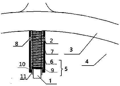
[0044] Such as figure 2 As shown, the difference between this embodiment and Embodiment 1 is that an inflation and deflation valve 19 is provided, which includes a valve 1 and an outer air passage 2 arranged outside the valve 1, and the valve 1 and the air pressure balance layer 3 connected to adjust the air pressure of the air pressure balance layer 3; the outer air channel 2 communicates with the hollow layer 4 for adjusting the air pressure of the hollow layer 4; the outer air channel 2 is provided with an isolating device 5 for isolating the hollow layer 4 It communicates with the outside world and opens the isolation device 5 to release the gas in the hollow layer 4 .

[0045] Among them, the valve 1 generally includes a valve body and a valve core; the valve core is located inside the valve body, and is mainly used to realize the air intake of the tire and prevent the tire from leaking; the outer wall of the valve 1 is provided with threads, which can be used to connect...


PUM


Abstract

The invention belongs to the technical field of transportation and specifically relates to a multi-block safety tire pressure balancing method. The multi-block safety tire pressure balancing method comprises the following steps of step 1, arranging an airbag layer and a hollow layer on a tire, wherein the airbag layer is arranged on the outer ring of the tire and consists of a plurality of independent small airbags; step 2, arranging a pressure balancing layer, which can inflate the airbag layer and the hollow layer in one direction, between the airbag layer and the hollow layer; step 3, inflating the pressure balancing layer to increase the pressure of the pressure balancing layer; and step 4, enabling the pressure balancing layer to inflate each small airbag of the airbag layer and the hollow layer in one direction so that pressures of the pressure balancing layer, the airbag layer and the hollow layer are kept consistent. By additionally arranging the pressure balancing layer, direct connection between the hollow layer and the airbag layer is avoided, the air tightness of the hollow layer is enhanced, and meanwhile, the hollow layer, which is in direct communication with the airbag layer, is prevented from leaking due to damages of individual small airbags of the airbag layer, and the running safety of the tire is enhanced.

Description

technical field [0001] The invention belongs to the technical field of transportation, and in particular relates to a multi-block safety tire air pressure balancing method. Background technique [0002] Nowadays, general-purpose car tires will inevitably encounter iron nails, glass and other sharp objects during driving, which will puncture the tire, causing air leakage and blowout. Tires bring huge workload and bring great difficulty and inconvenience to the driver. What's more, if a car blows out or leaks air during driving, it will cause the car to lose its balance during driving, making it difficult for the driver to grasp the direction and easily causing safety accidents, which is extremely dangerous. [0003] In order to prevent the tire from being punctured and cause the tire pressure to decrease, or even the danger of a tire blowout, a kind of run-flat tire was invented. Explosion-proof tires are provided with multiple inflation layers, and the inflation layer on t...

Claims


Application Information

Patent Timeline
Patent Type & Authority Patents(China)
IPC IPC(8): B60C5/20B60C23/00
CPCB60C5/20B60C23/001
Inventor 庞珽罗茜王荣平杨倜朱杰沈修泉
Owner 湖南邦链智能科技有限公司
Learn More