Telescopic suction pipe structure

A retractable straw technology, applied in the field of straws, can solve the problems of water spraying and scalding from straws, and achieve the effect of avoiding spraying and beautiful and simple design

Pending Publication Date: 2018-07-24
深圳市乐高婴童用品有限公司
View PDF6 Cites 1 Cited by
  • Summary
  • Abstract
  • Description
  • Claims
  • Application Information

AI Technical Summary

Problems solved by technology

[0008] The second straw structure is the most widely used water sealing method on the market. Its advantages are simple structure and easy to use. The disadvantage is that when the slide is opened too quickly, the straw will spray water outwards, and there is a risk of burns.

Method used


Image

  • Telescopic suction pipe structure
  • Telescopic suction pipe structure
  • Telescopic suction pipe structure

Examples


Embodiment 1

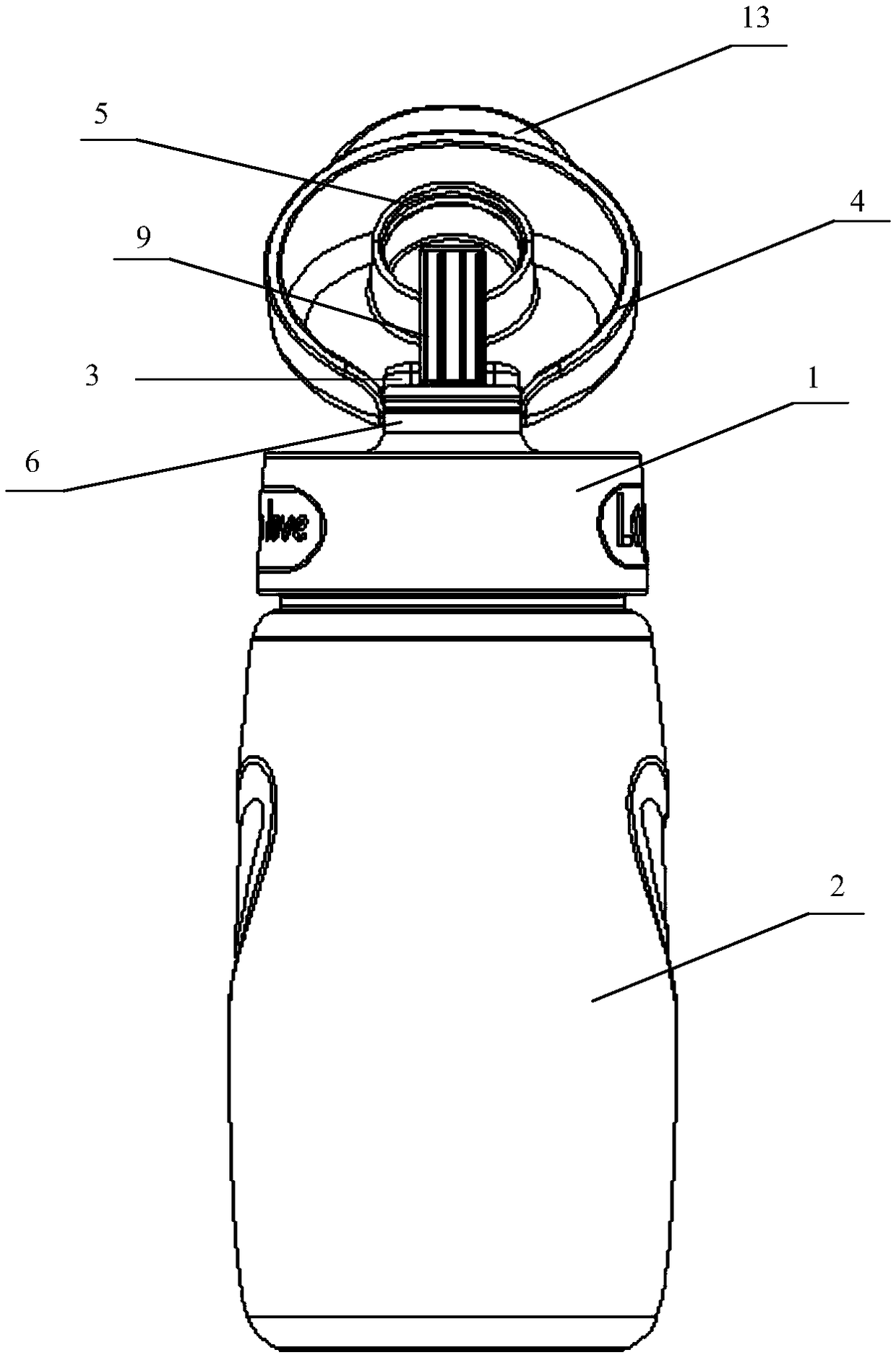
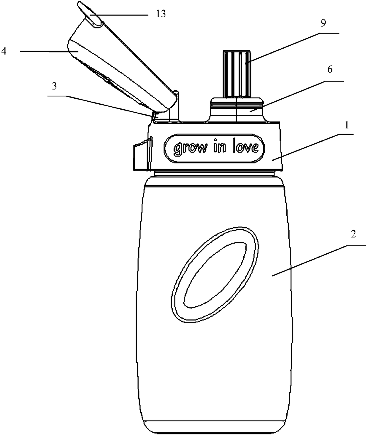
[0030] Such as Figure 1-6 The telescopic straw structure shown includes: an upper cover 1 , which removably covers the opening of the container 2 , and a rotating shaft 3 is provided at the upper end of the upper cover 1 .

[0031] A flip cover 4, the flip cover 4 is pivotally arranged on the rotating shaft 3 and can be pivoted to be opened and closed. The bottom of the flip cover 4 is provided with a sealing cover 5 extending downward. The flip cover cooperates with the upper cover to realize the basic structure of the flip container.

[0032] A hollow sealing cylinder 6, the sealing cylinder 6 vertically penetrates the upper cover 1 and its edge is higher than the plane where the upper cover 1 is located, when the flip cover 4 is closed, the sealing cover 5 is buckled with the opening above the sealing cylinder 6 seal. The sealing cylinder cooperates with the sealing cover to seal the suction pipe.

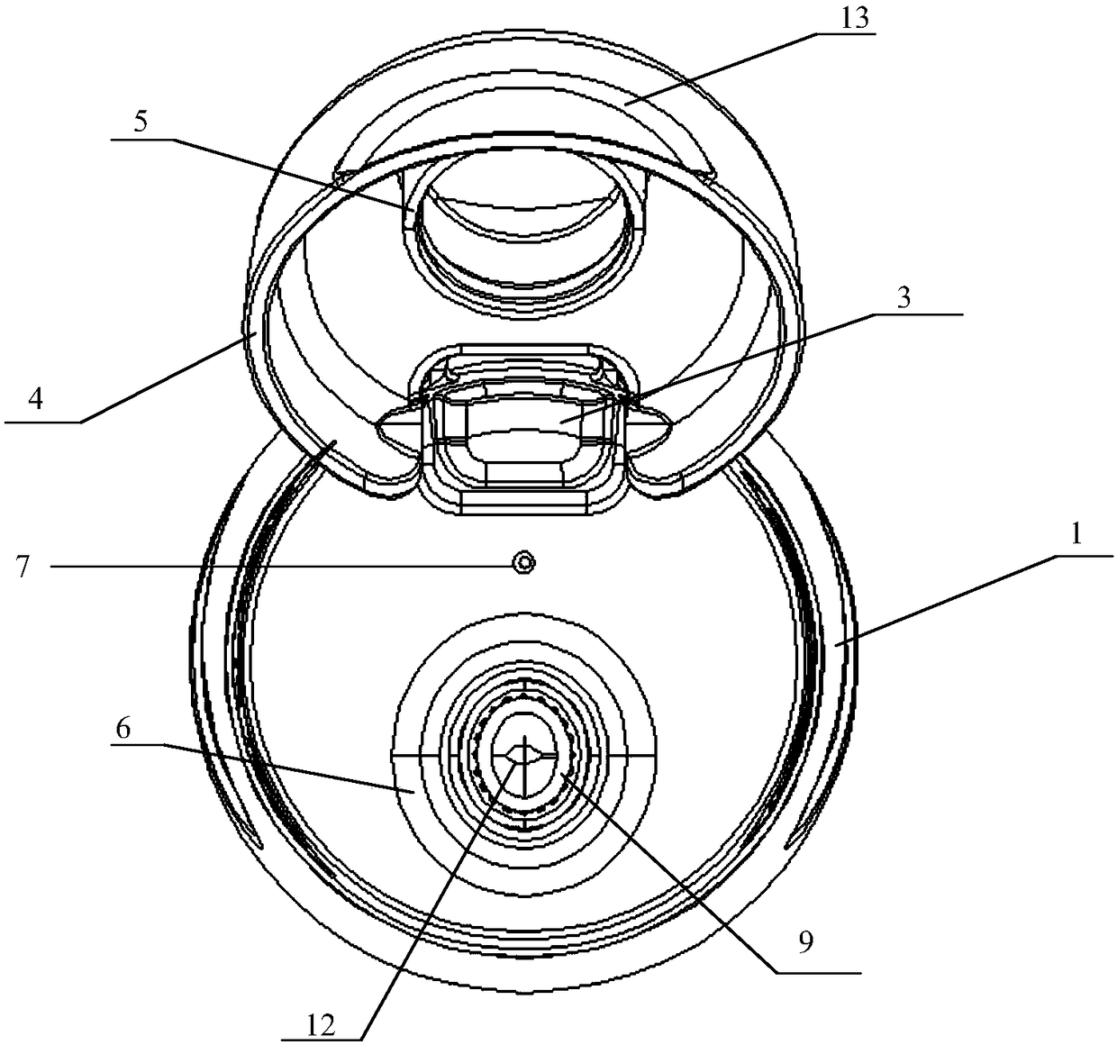
[0033] An air inlet 7, the air inlet 7 runs through the upper cover 1 a...

Embodiment 2

[0038] On the basis of embodiment 1, further, such as Figure 4 , 6 As shown, a sealing ring 10 is also included, and the sealing ring 10 is arranged between the upper cover 1 and the opening of the container 2 .

[0039] Further, the upper cover 1 is connected to the opening of the container 2 through a threaded structure.

[0040] Further, such as Figure 6 As shown, the air intake valve 8 and the suction pipe 9 are integrally formed. Since the air intake valve parts are small in size and are easy to lose, the integral molding of the air intake valve and the suction pipe can prevent the parts from being lost and can be integrally formed. Manufactured to reduce manufacturing costs.

[0041] Further, the intake valve 8 and the suction pipe 9 are made of silica gel. Such as Figure 6 As shown, in this embodiment, a laminated compression part is used, so the compression part is required to have good elasticity, and the silicone material has good elasticity and is safe and n...


PUM


Abstract

The invention relates to a telescopic suction pipe structure. The telescopic suction pipe structure comprises an upper cover, a clamshell cover, a hollow sealed cylinder, an air inlet, an air inlet valve and a suction pipe, wherein the clamshell cover is pivoted to the upper side of the upper cover, a sealing cover extending downward is arranged at the bottom of the clamshell cover, the hollow sealed cylinder vertically penetrates through the upper cover, the edge of the hollow sealed cylinder is higher than the plane where the upper cover is located, the air inlet runs through the upper cover, the air inlet valve is arranged at the bottom of the upper cover and communicated with the air inlet, the suction pipe comprises a suction nozzle part, a naturally-telescopic compression part and awater suction part which are sequentially connected from top to bottom, the suction pipe is fixed into the sealed cylinder, when the clamshell cover is closed, the clamshell cover presses the suctionpipe to be compressed downward and the sealing cover and an opening of the upper side of the sealed cylinder are buckled and sealed, and when the clamshell cover is opened, the suction pipe extends upward and the suction nozzle part is higher than the opening of the upper side of the sealed cylinder. The telescopic suction pipe structure is simple in structure and convenient to use, the suction nozzle part gently pops up after the clamshell cover is opened, the hot water spraying-out probability can be effectively avoided, and the spraying/leaking prevention effect is achieved.

Description

technical field [0001] The invention relates to a straw, in particular to a telescopic straw structure. Background technique [0002] For liquid containers such as kettles and feeding bottles in daily life, in order to facilitate drinking, straws are generally added to the mouth of the container. The following introduces the two common straw structure designs on the market: [0003] (1) Straw structure of clamshell container [0004] The flip of the flip-top container is generally provided with a downward-extending pressing piece. When the flip is closed, the pressing piece is driven to squeeze the straw nozzle downward, so that the straw is closed, thereby preventing the liquid from flowing out. [0005] The structure of the first type of straw seems simple, but because it is closed by the extrusion force of the pressing tablet, the upper cover is easily opened by the reaction force of the straw nozzle, so it is necessary to install a buckle structure on the upper cover to...

Claims


Application Information

Patent Timeline
Patent Type & Authority Applications(China)
IPC IPC(8): A47G21/18
CPCA47G21/189
Inventor 朱明勇
Owner 深圳市乐高婴童用品有限公司
Why Eureka
Try Eureka