Improved industrial dedusting equipment

A dust removal equipment and improved technology, applied in electrical components, coupling devices, circuits, etc., can solve the problems of inconvenient dust removal operation, easy occurrence of electric shock, affecting the passage of engineering vehicles or pedestrians, etc., to increase the safety of electricity consumption and avoid electric shock. effect of accident

Inactive Publication Date: 2018-07-24
东莞创想环保新材料科技有限公司
View PDF3 Cites 0 Cited by
  • Summary
  • Abstract
  • Description
  • Claims
  • Application Information

AI Technical Summary

Problems solved by technology

[0002] Industrial dust collectors are widely used in industrial production. However, industrial dust collectors have relatively high power. In some factories, they are specially equipped with power distribution boxes for plugging and power supply of dust collectors. However, these power distribution boxes have a single setting mode, and the conductive sheets inside Set relatively outside, this kind of conductive sheet is easy to be contacted by metal sheet or metal rod. Therefore, when people who lack safety awareness use metal sheet or rod to contact the conductive sheet, electric shock accidents are likely to occur; at the same time, the dust collector It is necessary to move the position frequently during the dust removal operation, so that it is easy to be affected by pulling the power supply line and cause the plug connection to become loose, resulting in power supply interruption, which brings great inconvenience to the dust removal operation. In addition, most of the existing distribution boxes are fixed. It is installed on the ground, which makes the occupied area larger and seriously affects the traffic of engineering vehicles or pedestrians

Method used


Image

  • Improved industrial dedusting equipment
  • Improved industrial dedusting equipment
  • Improved industrial dedusting equipment

Examples


Embodiment Construction

[0024] All features disclosed in this specification, or steps in all methods or processes disclosed, may be combined in any manner, except for mutually exclusive features and / or steps.

[0025] Any feature disclosed in this specification (including any appended claims, abstract and drawings), unless expressly stated otherwise, may be replaced by alternative features which are equivalent or serve a similar purpose. That is, unless expressly stated otherwise, each feature is one example only of a series of equivalent or similar features.

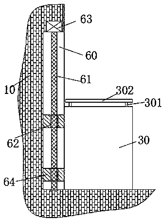
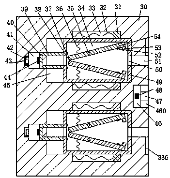
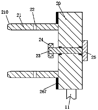
[0026] like Figure 1 to Figure 4As shown, an improved industrial dust removal equipment of the device of the present invention includes a cabinet 30 arranged on a wall 10 that can slide up and down through a lifting assembly and a plug head 20 connected to the dust collector through a cable 11. The plug The middle end of the head 20 is provided with a left and right rotating cavity, and a rotating column 23 is rotatably installed in the rota...


PUM


Abstract

The invention provides improved industrial dedusting equipment comprising a case which can be arranged on the wall in an upward and downward sliding way through an elevating component and a plug pin head which is connected with a deduster through a cable. The middle end of the plug pin head is provided with a left-and-right communicated rotating cavity which is rotatably provided with a rotating column. The right end of the rotating column stretches out of the plug pin head and is fixedly provided with a handle. The left end of the rotating column stretches out of the plug pin head and is vertically and symmetrically provided with iron sheets. The left end surface of the plug pin head is fixedly and vertically and symmetrically provided with plug shafts. The plug shafts are provided with vertically communicated plug holes. The top end surface of the case is fixedly provided with a dustproof plate through a fixing rod. The case is vertically and symmetrically provided with left-and-right extending slide cavities. The right end wall of each slide cavity is provided with a first plug slot which is communicated with the outside and cooperated with each plug shaft.

Description

technical field [0001] The invention relates to the technical field of industrial dust removal, in particular to an improved industrial dust removal equipment. Background technique [0002] Industrial dust collectors are widely used in industrial production. However, industrial dust collectors have relatively high power. In some factories, they are specially equipped with power distribution boxes for plugging and power supply of dust collectors. However, these power distribution boxes have a single setting mode, and the conductive sheets inside Set relatively outside, this kind of conductive sheet is easy to be contacted by metal sheet or metal rod. Therefore, when people who lack safety awareness use metal sheet or rod to contact the conductive sheet, electric shock accidents are likely to occur; at the same time, the dust collector It is necessary to move the position frequently during the dust removal operation, so that it is easy to be affected by pulling the power suppl...

Claims


Application Information

Patent Timeline
Patent Type & Authority Applications(China)
IPC IPC(8): H01R13/703H01R13/639
CPCH01R13/7035H01R13/639
Inventor 覃日雄马浩晓
Owner 东莞创想环保新材料科技有限公司
Why Eureka
Try Eureka