Detachable vibrator mount for mobile phone

A vibrator and mounting base technology, which is applied in the field of detachable mobile phone vibrator mounting bases, can solve problems such as damage, vibration energy reduction, and vibration effect weakening, so as to reduce maintenance and replacement costs, increase service life, and save time and labor for installation. Effect

Active Publication Date: 2018-07-24
泾县凡泽科技服务有限公司
View PDF3 Cites 0 Cited by
  • Summary
  • Abstract
  • Description
  • Claims
  • Application Information

AI Technical Summary

Problems solved by technology

Although the rubber sheath 3 can provide sufficient frictional force between the vibrator 2 and the base clamp 11, so that the vibrator 2 will not disengage from the base clamp 11 when vibrating, but because the rubber sheath 3 has the characteristic of slowing down the vibration, when When the vibrator 2 vibrates

Method used


Image

  • Detachable vibrator mount for mobile phone
  • Detachable vibrator mount for mobile phone
  • Detachable vibrator mount for mobile phone

Examples


Embodiment 1

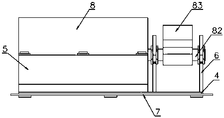
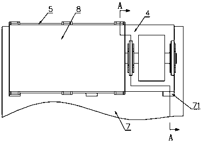
[0031] Embodiment 1: A detachable mobile phone vibrator mount, such as Figure 2~Figure 10As shown, it includes a base 4, a motor fixing block 5 and a motor shaft mounting block 6. The base 4 includes a base plate 41 and a clamping block 42. The clamping block 42 is arranged below one end of the base plate 41. The clamping block 42 is L-shaped. A fixing groove 43 is formed between the lateral edge of the block 42 and the substrate 41, and the distance between the lateral edge of the clamp block 42 and the substrate 41 corresponds to the thickness of the main board 7, that is, the width of the groove 43 corresponds to the thickness of the main board 7, The shape of the groove bottom of the draw-in groove 43 is U-shaped, and three mounting holes 71 are equidistantly arranged along the axial direction of the motor fixing block 5 on the main board 7. The width of 71 is greater than the length of the diagonal line between the vertical side and the horizontal side corner of the clam...

Embodiment 2

[0032] Embodiment 2: The difference from Embodiment 1 is that both the motor fixing block 5 and the motor shaft mounting block 6 are welded on the upper surface of the base plate 41 of the base 4 .

Embodiment 3

[0033] Embodiment 3: The difference from Embodiment 1 is that both the motor fixing block 5 and the motor shaft mounting block 6 are adhered to the upper surface of the base plate 41 of the base 4 .


PUM


Abstract

A detachable vibrator mount for a mobile phone comprises a base, a motor fixing block and a motor shaft mounting block, wherein the base comprises a substrate and a clamping block, the clamping blockis arranged below one end of the substrate, a fixing card slot is formed between the lateral side of the clamping block and the substrate, the width of the fixing card slot corresponds to the thickness of a main board, the base is fixedly installed on the main board by the fixing card slot, the motor fixing block is fixedly mounted on the upper surface of the substrate of the base, the motor is fixedly installed in the motor fixing block, the motor shaft mounting block is of a detachable split type, the motor shaft mounting block is parallel to the motor fixing block, the motor shaft can be rotatably and horizontally mounted on the motor shaft mounting block, and an eccentric wheel is fixedly sleeved on the motor shaft. By using the vibrator mount provided by the invention, the mobile communication device may obtain better vibration effects. As the motor is detachable, the invention is low in replacement and repair cost, simple in structure, good in connection strength, long in servicelife of the motor, and time-saving as well as labor-saving in installation.

Description

technical field [0001] The invention relates to the technical field of mobile phones, in particular to a detachable mobile phone vibrator mounting seat. Background technique [0002] With the increasing number of people using mobile communication devices (such as mobile phones and pagers), mobile communication devices are almost ubiquitous in our daily life. As a modern communication tool, mobile phones have completely entered all aspects of people's lives and become an indispensable communication tool in people's work and life. However, due to the widespread use of mobile communication devices, it often brings some unpleasant adverse effects, such as : Disturbing an environment that should be quiet, of which the movie theater is a prime example. Therefore, in order to prevent these unexpected interferences and at the same time provide a mobile communication device that is more adaptable to the usage occasions, manufacturers usually add vibrators to these mobile communicati...

Claims


Application Information

Patent Timeline
IPC IPC(8): H04M1/02
CPCH04M1/0249H04M1/026
Inventor 田金金周仁伟
Owner 泾县凡泽科技服务有限公司
Why Eureka
Try Eureka