Sound cavity device and mobile terminal

A mobile terminal and sound chamber technology, applied in the field of sound chambers, can solve the problems of mobile phones with difficult bass effects, narrow frequency bands, and difficulty in improving sound effects, and achieve the effects of improving acoustic performance, portability, and reducing size

Pending Publication Date: 2018-07-24
SHANGHAI TRANSSION CO LTD
View PDF0 Cites 0 Cited by
  • Summary
  • Abstract
  • Description
  • Claims
  • Application Information

AI Technical Summary

Problems solved by technology

[0002] Existing mobile terminals, such as mobile phones, are basically equipped with sound cavity devices for playing sound. The sound cavity devices of existing mobile phones generally use ordinary materials and smooth inner walls or box structures with integrated speakers and cavities. , because the music sound in the low-frequency part has a great influence on the sound quality, the lower the low-frequency resonance point, the more pleasing the subjective sound effect, and the bass effect of the mobile phone with the above structure is difficult to be improved from the later stage
Specifically, affected by the size of the mobile phone, the space reserved for the sound chamber device is getting smaller and smaller. The smaller the cavity, the higher the low-frequency resonance point, the worse the hearing of the mobile phone, the narrower the frequency band, and the lower the sound pressure level. It will be limited. If you want to increase the volume, you need an additional power amplifier to support it, which not only increases the cost but also makes it difficult to improve the sound effect. Therefore, the design of the sound cavity device of the mobile terminal has put forward higher and higher requirements.
[0003] For a traditional speaker, its volume is larger than that of a mobile phone. The cavity of the speaker can accommodate devices such as inverter tubes or resonant basins to improve the low-frequency effect of the cavity. However, due to its large size, it is less portable.

Method used


Image

  • Sound cavity device and mobile terminal
  • Sound cavity device and mobile terminal
  • Sound cavity device and mobile terminal

Examples


Embodiment Construction

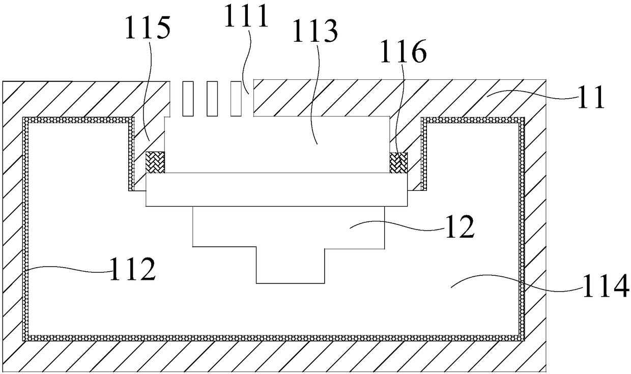
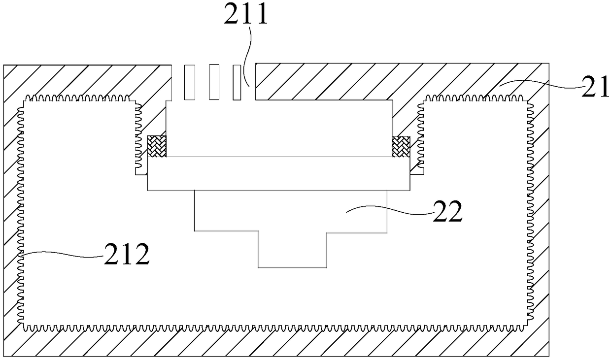
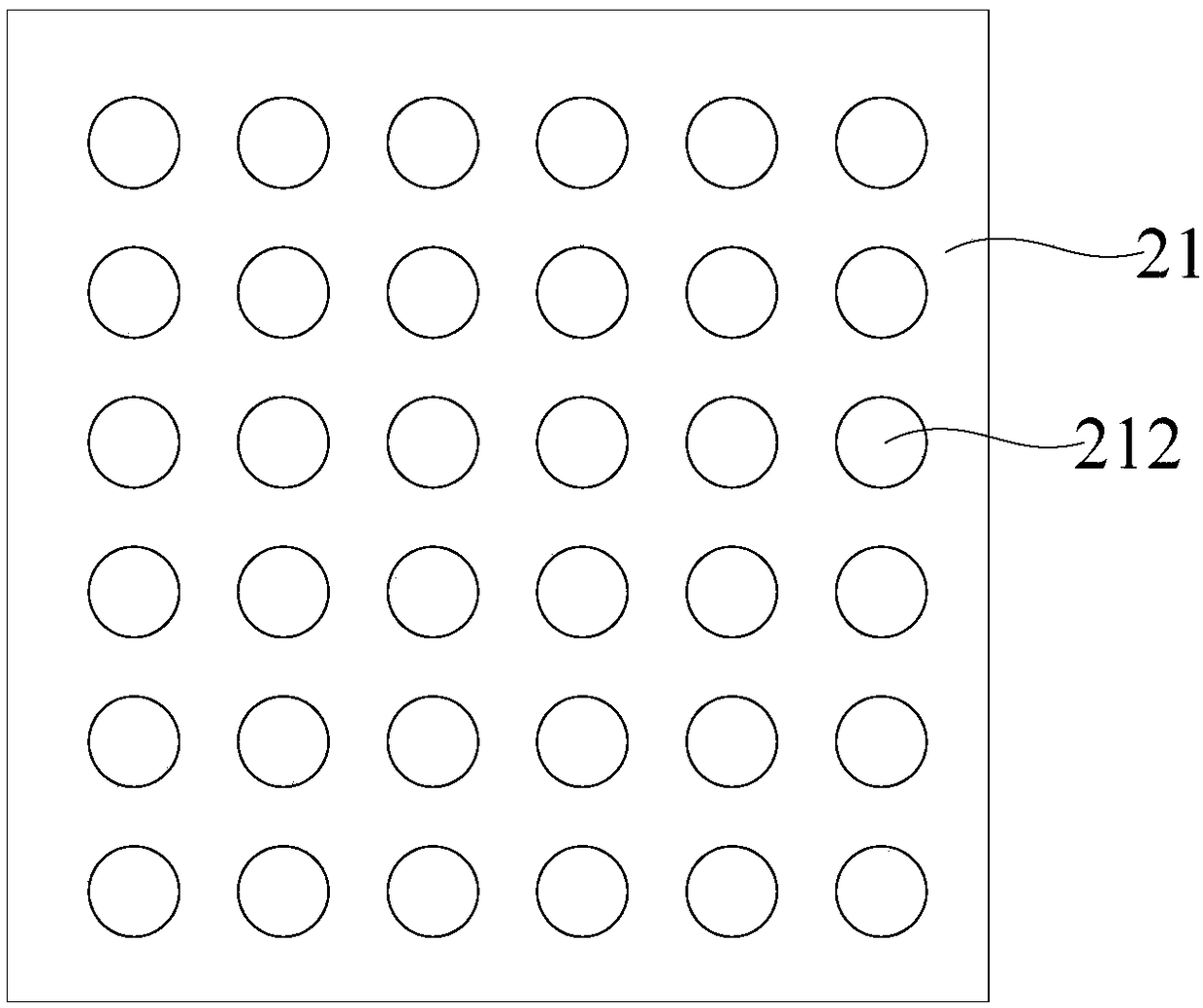
[0025] Example embodiments will now be described more fully with reference to the accompanying drawings. Example embodiments may, however, be embodied in many forms and should not be construed as limited to the embodiments set forth herein; rather, these embodiments are provided so that this disclosure will be thorough and complete, and will fully convey the concept of example embodiments to those skilled in the art. The same reference numerals denote the same or similar structures in the drawings, and thus their repeated descriptions will be omitted.

[0026] The words expressing position and direction described in the present invention are all described by taking the accompanying drawings as an example, but changes can also be made according to needs, and all changes are included in the protection scope of the present invention. The accompanying drawings of the present invention are only used to illustrate the relative positional relationship, and the layer thickness of som...


PUM

PropertyMeasurementUnit
Thicknessaaaaaaaaaa
Opening diameteraaaaaaaaaa
Depthaaaaaaaaaa

Abstract

The invention discloses a sound cavity device and a mobile terminal. The sound cavity device comprises a cavity and a loudspeaker, wherein the cavity is provided with a sound outlet hole; the loudspeaker is positioned in the cavity; a sound suction structure is arranged on the inner wall of the cavity. The sound cavity device can meet the acoustic performance requirement of the small-dimension cavity design. For a conventional sound box using the sound cavity device, the acoustic performance and the portability can be improved at the same time under the condition of size reduction.

Description

technical field [0001] The present invention relates to the field of sound chamber technology, in particular to a sound chamber device and a mobile terminal. Background technique [0002] Existing mobile terminals, such as mobile phones, are basically equipped with sound cavity devices for playing sound. The sound cavity devices of existing mobile phones generally use ordinary materials and smooth inner walls or box structures with integrated speakers and cavities. , because the music sound in the low-frequency part has a great influence on the sound quality, the lower the low-frequency resonance point, the more pleasing the subjective sound effect, but the bass effect of the mobile phone with the above structure is difficult to be improved from the later stage. Specifically, affected by the size of the mobile phone, the space reserved for the sound chamber device is getting smaller and smaller. The smaller the cavity, the higher the low-frequency resonance point, the worse ...

Claims


Application Information

Patent Timeline
IPC IPC(8): H04R9/06H04R9/02
CPCH04R9/06H04R9/02H04R2400/11
Inventor 庞杰许逸君
Owner SHANGHAI TRANSSION CO LTD
Why Eureka
Try Eureka