
A separate installation type split flow centrifugal device

A centrifugal device and separate technology, applied in centrifuges and other directions, can solve problems such as difficult installation, time-consuming filling, cumbersome efficiency, etc., and achieve the effects of compact structure design, easy installation and adjustment, and high detection efficiency

Active Publication Date: 2020-10-16
浙江杰迪泵业有限公司
View PDF11 Cites 0 Cited by
  • Summary
  • Abstract
  • Description
  • Claims
  • Application Information

AI Technical Summary

Problems solved by technology

[0003] In order to solve the above problems, the present invention is proposed, which overcomes the problems of low efficiency, poor precision, and time-consuming filling due to the manual filling of the currently used centrifugal equipment, and solves the problems of the currently used centrifugal equipment due to the precise filling The structure is a split structure, which needs to be reloaded during use, resulting in cumbersome use and low efficiency. It improves the current centrifugal equipment. Due to the unstable installation structure and difficult installation, it causes jumping in the centrifugal test, which affects the test results and equipment safety. , so that the present invention has the advantages of compact structure design, easy installation and adjustment, good interchangeability, simplified process, accurate samples, high detection efficiency, and good quality.

Method used


Image

  • A separate installation type split flow centrifugal device
  • A separate installation type split flow centrifugal device
  • A separate installation type split flow centrifugal device

Examples


Embodiment Construction

[0017] The following will clearly and completely describe the technical solutions in the embodiments of the present invention with reference to the accompanying drawings in the embodiments of the present invention. Obviously, the described embodiments are only some, not all, embodiments of the present invention. Based on the embodiments of the present invention, all other embodiments obtained by persons of ordinary skill in the art without making creative efforts belong to the protection scope of the present invention.

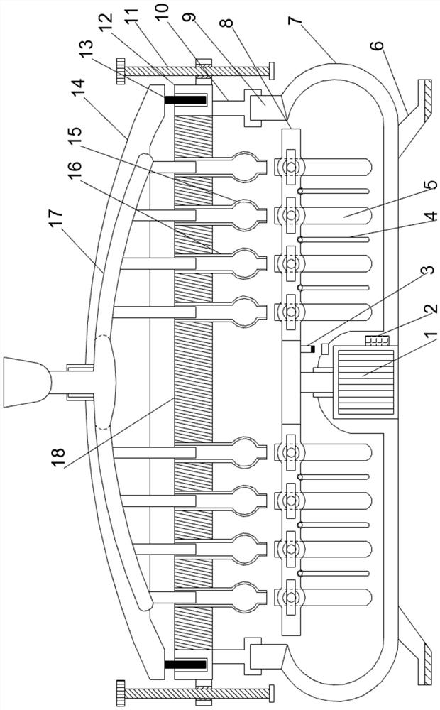
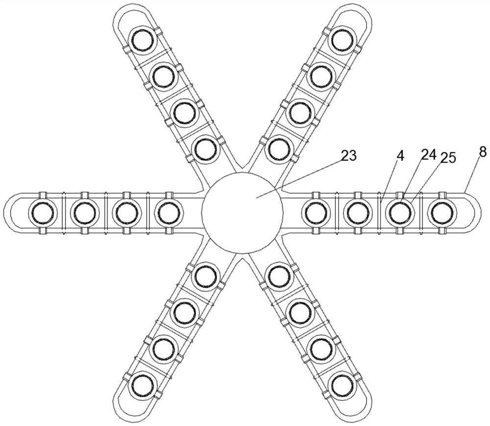
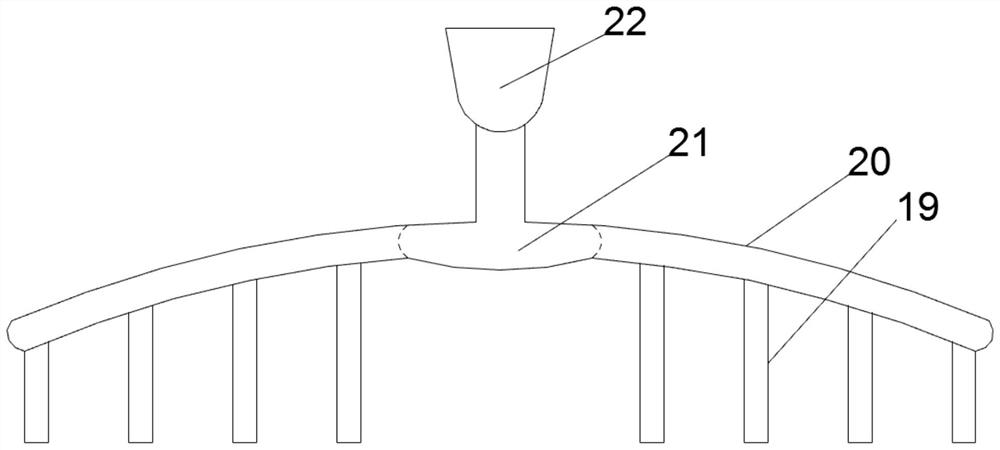
[0018] see Figure 1~3 , in an embodiment of the present invention, a split-mounted centrifugal device, comprising an arc-shaped centrifugal installation cylinder 7, the lower end edge of the arc-surface centrifugal installation cylinder 7 is provided with a number of support installation columns 6 at equal angles, and the support installation The lower end of the column 6 is covered with a rubber anti-slip mat horizontally, and the middle position of the lowe...


PUM


Abstract

The invention discloses a split installation type shunt centrifugal device. The split installation type shunt centrifugal device comprises a cambered surface centrifugal mounting barrel. A motor mounting tube is vertically upwards arranged in the middle position of the lower end of the cambered surface centrifugal mounting barrel. A centrifugal motor is vertically embedded in the middle position of the interior of the motor mounting tube. A centrifugal rotary shaft is arranged in the middle position of the upper end of the centrifugal motor and vertically upwards extends out of the motor mounting tube. A centrifugal mounting disk is concentrically and horizontally arranged at the upper end of the centrifugal rotary shaft. A plurality of centrifugal mounting frames are outwards horizontallyarranged on the centrifugal mounting disk at equal angles. Loading balance plates which are horizontally arranged through rotary shafts arranged in a front-back penetrating mode are horizontally andequidistantly arranged in each centrifugal mounting frame. A locating mounting ring is vertically upwards arranged at the upper end of the cambered surface centrifugal mounting barrel. The split installation type shunt centrifugal device has the advantages that structure design is compact, installation and adjustment are easy and convenient, the interchangeability is good, the process is simplified, samples are accurate, the detection efficiency is high, and the quality is good.

Description

technical field [0001] The invention relates to a detection device, in particular to a split installation type split flow centrifugal device. Background technique [0002] Centrifugal testing equipment is a machine that uses centrifugal force to separate components in a mixture of liquid and solid particles or liquid and liquid. Centrifugal testing equipment is mainly used to separate solid particles in suspension from liquid, or separate the two components in emulsion Different densities and immiscible liquids are separated. It can also be used to remove liquids in wet solids. The special ultra-speed tube separator can also separate gas mixtures of different densities, using solid particles of different densities or particle sizes in liquids. The characteristics of the different settling velocities. [0003] In order to solve the above problems, the present invention is proposed, which overcomes the problems of low efficiency, poor precision, and time-consuming filling due...

Claims


Application Information

Patent Timeline
Patent Type & Authority Patents(China)
IPC IPC(8): B04B5/04B04B11/04
CPCB04B5/0414B04B11/04
Inventor 徐永香
Owner 浙江杰迪泵业有限公司
Learn More