
Rope sheave groove pressing machine

A technology of groove pressing machine and rope pulley, applied in the field of groove pressing machine, can solve the problems of low efficiency and accidental hand injury of employees, and achieve the effects of high safety performance, rapid groove pressing processing and reasonable structure

Inactive Publication Date: 2018-07-27
河南省银河起重机械有限公司
View PDF4 Cites 0 Cited by
  • Summary
  • Abstract
  • Description
  • Claims
  • Application Information

AI Technical Summary

Problems solved by technology

The traditional rope wheel grooving machine mainly relies on manpower in the process of grooving the rope wheel. This kind of production method is inefficient, and it is easy to accidentally injure the hands of employees by the machine.

Method used


Image

  • Rope sheave groove pressing machine
  • Rope sheave groove pressing machine

Examples


Embodiment Construction

[0018] The following will clearly and completely describe the technical solutions in the embodiments of the present invention with reference to the accompanying drawings in the embodiments of the present invention. Obviously, the described embodiments are only some, not all, embodiments of the present invention.

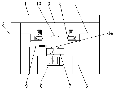
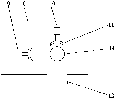
[0019] refer to Figure 1-2 , a rope pulley grooving machine, including a crossbeam 1, two support columns 2 and an operating table 6, the crossbeam 1 is fixedly connected to the tops of the two support columns 2, the operation table 6 is located directly below the crossbeam 1, and the top of the crossbeam 1 A top column 3 is fixed on one side, and one end of the top column 3 is rotatably connected to a first fixed plate 13. The side where the two support columns 2 are close to each other is fixed with a first hydraulic cylinder 4, and the two first hydraulic cylinders 4 are close to each other. One end of each is provided with a mounting groove, and the inside of th...


PUM


Abstract

The invention discloses a rope sheave groove pressing machine which comprises a cross beam, two supporting columns and an operating floor. The cross beam is fixedly connected with the tops of the twosupporting columns, and the operating floor is located under the cross beam. A jacking column is fixed to one side of the cross beam, and one end of the jacking column is rotationally connected with afirst fixing disc. First hydraulic cylinders are fixed to the sides, close to each other, of the two supporting columns correspondingly, and mounting grooves are formed in the sides, close to each other, of the two first hydraulic cylinders correspondingly. Groove pressing wheels are arranged in the mounting grooves, and a first push rod motor and a second push rod motor are arranged at the top of the operating floor. Limiting blocks are fixed to one ends of the first push rod motor and the second push rod motor correspondingly, and a cavity is formed in the operating floor and internally provided with a rotary table and a second hydraulic cylinder. The rope sheave groove pressing machine is reasonable in structure, ingenious in design, capable of quickly conducting groove pressing machining on a rope sheave, easy to operate, high in safety performance and easy to use and popularize.

Description

technical field [0001] The invention relates to the technical field of notching machines, in particular to a sheave notching machine. Background technique [0002] The rope pulley refers to the pulley that can be used to hang the wire rope. In order to ensure that the wire rope can be hung on the surface of the rope pulley stably, a groove is provided on the surface of the rope pulley to facilitate the wire rope to be stuck in the groove. [0003] Grooving machine, that is, a machine used to groove the surface of an object. In the manufacturing process of the sheave, in order to press the groove on the surface of the sheave, a sheave groove machine is generally used. The traditional rope wheel grooving machine mainly relies on manpower to control the rope wheel grooving process. This kind of production method is inefficient, and it is easy to accidentally injure employees' hands by the machine. Contents of the invention [0004] The purpose of the present invention is to...

Claims


Application Information

Patent Timeline
Patent Type & Authority Applications(China)
IPC IPC(8): B21D17/04
CPCB21D17/04
Inventor 徐家祥崔旭太常微昌
Owner 河南省银河起重机械有限公司
Learn More