Novel charging pile convenient to transfer and move

A charging pile and convenient technology, applied in the direction of electric vehicle charging technology, charging station, transportation and packaging, etc., can solve the problems of waste of resources, increase the cost of charging, and high cost, achieve convenient transportation and movement, increase enterprise costs, avoid shaking effect

Pending Publication Date: 2018-07-27
安吉华众汽车修理有限公司
View PDF1 Cites 3 Cited by
  • Summary
  • Abstract
  • Description
  • Claims
  • Application Information

AI Technical Summary

Problems solved by technology

[0002] Electric vehicle charging pile is a power station for electric vehicles. Its function is similar to that of a fuel dispenser in a gas station. Each charging pile is equipped with a charging plug. The charging pile can charge various types of electric vehicles according to different voltage levels. The car charging pile adopts AC and DC power supply methods, and requires a special charging card to be used. The display screen of the charging pile can display data such as charging amount, cost, and charging time. The cost of charging piles is relatively high. Generally, the price of a charging pile is Tens of thousands or even hundreds of thousands are mainly installed in the parking lot. The existing charging piles are at risk of being stolen, and due to the high cost, the general parking lot only sets a small number, but as electric vehicles become more and more widespread The demand for charging piles is increasing, and the charging piles fixed in some fixed parking spaces cannot meet the needs of the public. However, if one charging pile is installed for every one or two parking spaces, it will cause an oversupply situation, which will cause resources Waste, especially the charging piles in the open air are easily damaged by the wind and the sun, which increases the charging cost. In the prior art, for example, the invention patent with application number 201521066146.2 includes the charging pile body, which is a charging pile with a switchable door , the charging pile pulley, which is located at the bottom of the charging pile body, which is at least four rotatable pulleys for supporting, and the fixing seat, which is fixed on the ground, is connected to the charging pile body by communication, and the connection lock , which is arranged on the fixing seat, and is used to lockably connect the charging pile body and the fixing seat; a lock hole, which is arranged on the charging pile body at a position corresponding to the connection lock; a reminder button, which Located on the surface of the fixed seat, the switch handle is arranged on one side of the switch door of the charging pile body, the control box is located on the switch door of the charging pile body, and is arranged on the control box for The liquid crystal screen for displaying charging information, the switch button for opening and closing, and the card swiping induction area for identifying and recording IC cards, although the structure of the invention is simple, there are many deficiencies and defects. In the existing equipment, the charging pile body There are defects in the design. The height of the charging pile body cannot be adjusted when it is in use. In addition, the connection between the charging pile body and the fixed base is unstable. In view of these situations, in order to avoid the above-mentioned technical problems, it is necessary to provide a new charging pile that is convenient for transfer and movement to overcome the problems in the prior art. said defect of

Method used


Image

  • Novel charging pile convenient to transfer and move
  • Novel charging pile convenient to transfer and move
  • Novel charging pile convenient to transfer and move

Examples


Embodiment Construction

[0019] The following will clearly and completely describe the technical solutions in the embodiments of the present invention with reference to the accompanying drawings in the embodiments of the present invention. Obviously, the described embodiments are only some, not all, embodiments of the present invention. Based on the embodiments of the present invention, all other embodiments obtained by persons of ordinary skill in the art without making creative efforts belong to the protection scope of the present invention.

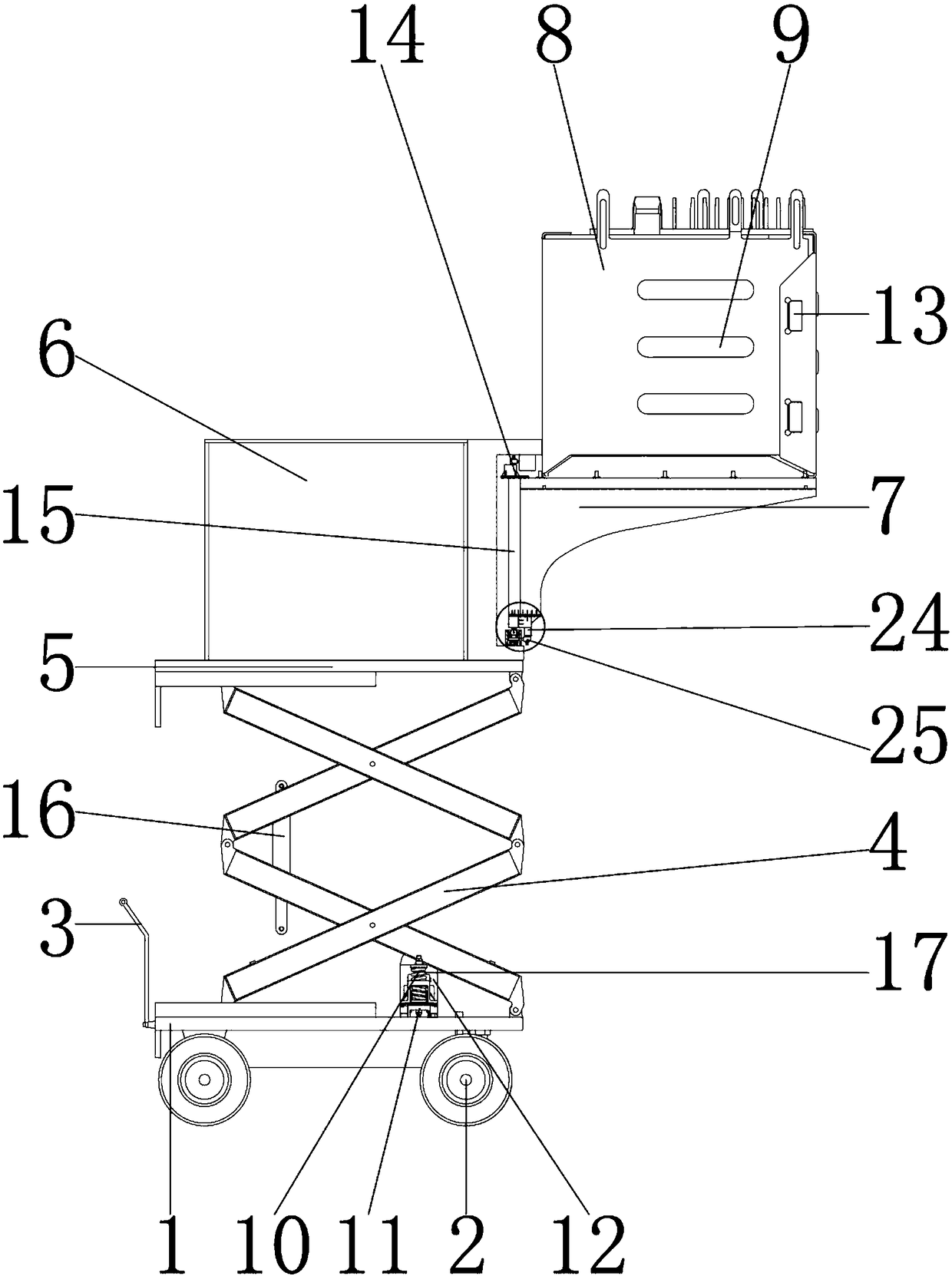
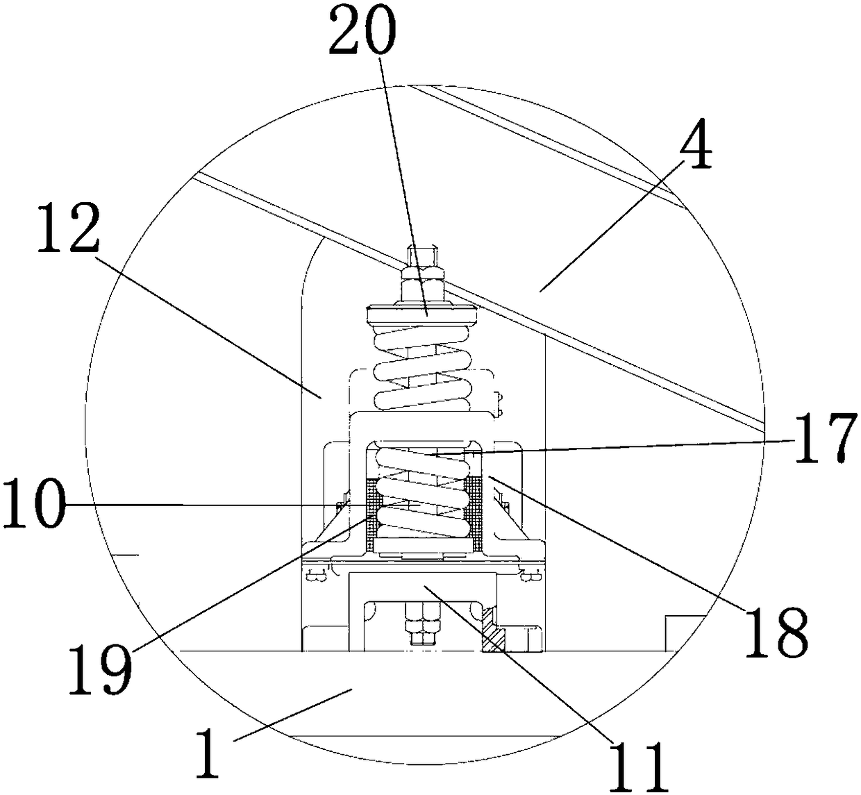
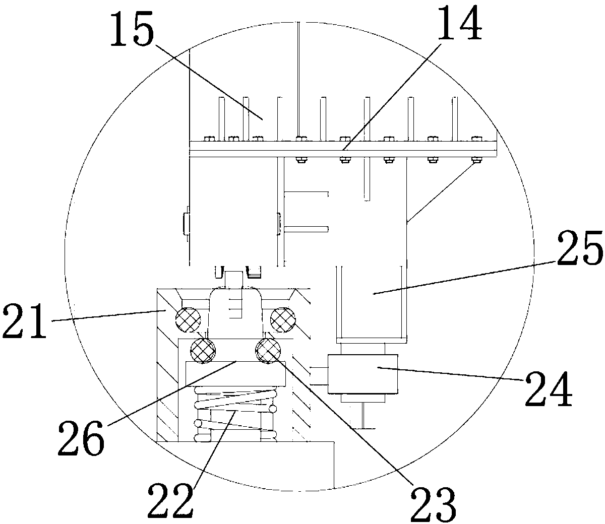
[0020] see Figure 1-3, the present invention provides a technical solution: a new charging pile convenient for transfer and movement, including a base plate 1 for installing rollers 2, the outer wall of the base plate 1 is equipped with a roller 2, and the rollers 2 are used to drive the base plate 1 to move, and the rollers 2 The inner wall of the base plate 1 is movably connected with the outer wall of the base plate 1. A push handle 3 is installed on the l...


PUM


Abstract

The invention discloses a novel charging pile convenient to transfer and move. The novel charging pile comprises a bottom board. Idler wheels are installed on the outer wall of the bottom board. The inner walls of the idler wheels are movably connected with the outer wall of the bottom board. A push handle is installed on the outer wall on the left side of the bottom board. The outer wall on the right side of the push handle is connected with the outer wall on the left side of the bottom board. A shell is installed on the upper surface of the bottom board. The lower surface of the shell is connected with the upper surface of the bottom board. By the adoption of the novel charging pile convenient to transfer and move, through cooperation between the bottom board and the push handle and under the effect of the idler wheels, the bottom board can be pushed forwards or backwards through the push handle, a front box and a rear box are moved or transferred to a place needing to arrive, the bottom board is moved faster under the effect of the idler wheels, the product quality of the novel charging pile convenient to transfer and move is improved, the purchasing cost of a user is saved, resource waste of the novel charging pile convenient to transfer and move is avoided, and the novel charging pile convenient to transfer and move is suitable for use and popularization.

Description

technical field [0001] The invention relates to the technical field of charging piles, in particular to a new charging pile that is convenient for transfer and movement. Background technique [0002] Electric vehicle charging pile is a power station for electric vehicles. Its function is similar to that of a fuel dispenser in a gas station. Each charging pile is equipped with a charging plug. The charging pile can charge various types of electric vehicles according to different voltage levels. The car charging pile adopts AC and DC power supply methods, and requires a special charging card to be used. The display screen of the charging pile can display data such as charging amount, cost, and charging time. The cost of charging piles is relatively high. Generally, the price of a charging pile is Tens of thousands or even hundreds of thousands are mainly installed in the parking lot. The existing charging piles are at risk of being stolen, and due to the high cost, the general...

Claims


Application Information

Patent Timeline
Patent Type & Authority Applications(China)
IPC IPC(8): B60L11/18
CPCB60L53/31B60L53/35Y02T10/70Y02T10/7072Y02T90/12
Inventor 张业勋
Owner 安吉华众汽车修理有限公司
Why Eureka
Try Eureka