LED project lamp

A technology of LED floodlights and lamp bodies, which is applied in the direction of light sources, electric light sources, semiconductor devices of light-emitting elements, etc., which can solve the problems of cumbersome installation and fixing operations, looseness, and limited installation structures, and achieve safe and stable locking and easy operation. Convenient, safe and stable power on

Inactive Publication Date: 2018-07-31
钟海迪
View PDF0 Cites 2 Cited by
  • Summary
  • Abstract
  • Description
  • Claims
  • Application Information

AI Technical Summary

Problems solved by technology

[0002] Due to the limited installation structure, the existing LED floodlights can only be used for outdoor lighting. If they are to be installed inside the room, they are all fixed by screws or bolts during the installation process. There will be loose phenomenon during the use process, and the installation and fixing operation is more cumbersome

Method used


Image

  • LED project lamp
  • LED project lamp
  • LED project lamp

Examples


Embodiment Construction

[0021] The preferred embodiments of the present invention will be described in detail below in conjunction with the accompanying drawings, so that the advantages and features of the present invention can be more easily understood by those skilled in the art, so as to define the protection scope of the present invention more clearly.

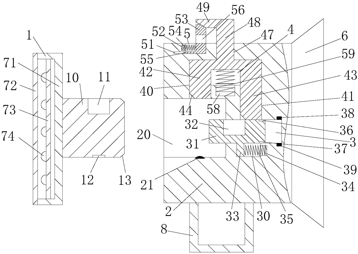
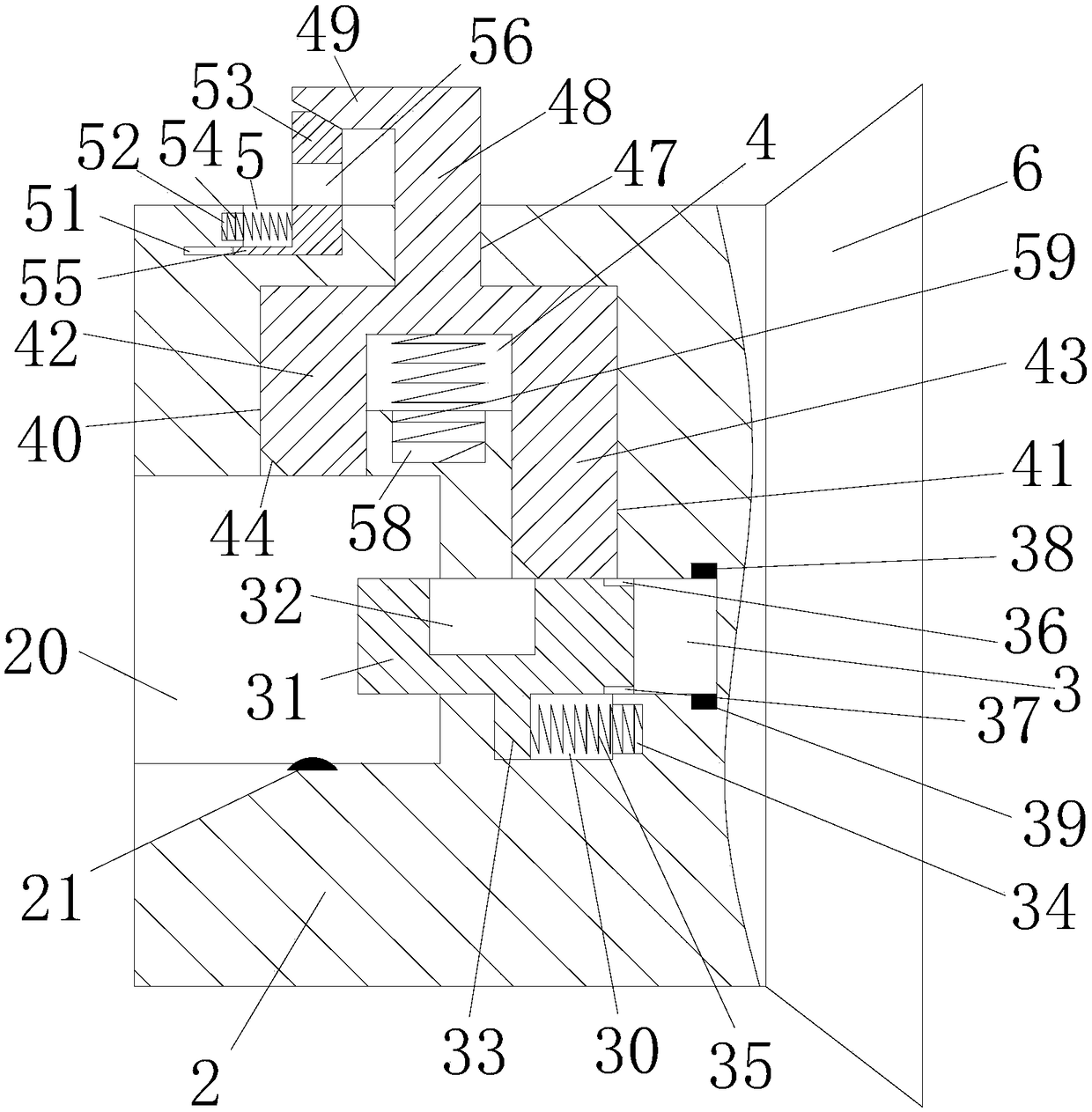
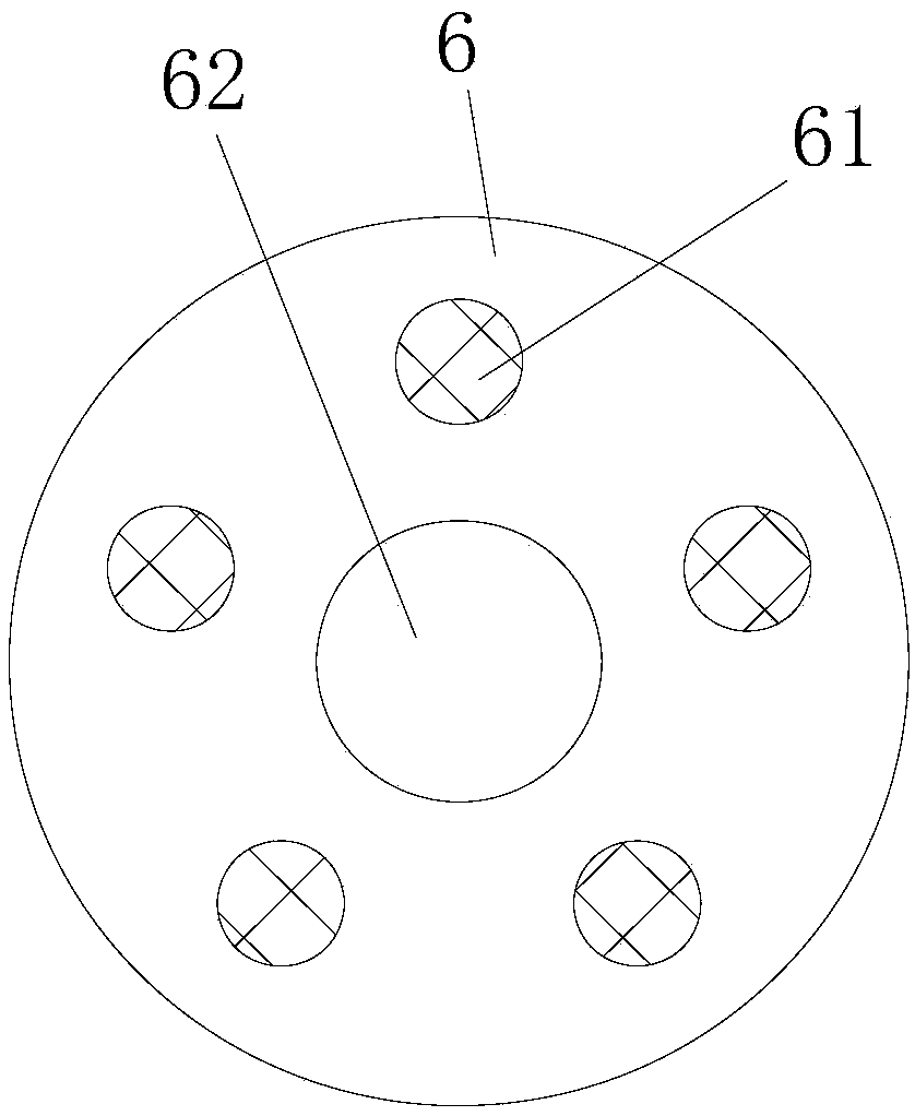
[0022] refer to Figure 1 to Figure 4 As shown, an LED floodlight of the present invention includes a lamp body 1, a connecting seat 2, a suction cup 6 and a bracket 8. The lamp body 1 is located on the left side of the connecting seat 2, the suction cup 6 is located on the right side of the connecting seat 2, and the bracket 8 is located on the On the lower side of the connecting base 2, the connecting base 2 is fixed on the wall through the suction cup 6 or placed on the table through the bracket 8. The lamp body 1 is installed on the connecting seat 2, and the left end surface of the connecting seat 2 is provided with a card insertion slot 20,...


PUM


Abstract

The invention discloses LED project lamp. The LED project lamp comprises a lamp body, a connecting base, a suction cup and a support. The lamp body is located on the left side of the connecting base.The suction cup is located on the right side of the connecting base. The support is located on the lower side of the connecting base. The connecting base is fixed to a wall through the suction cup oris arranged on a table top through the support. An insertion-clamping groove is formed in the left end face of the connecting base. An elastic power plug is arranged in the middle of the bottom end wall of the insertion-clamping groove. A first longitudinal sliding groove is formed in the middle of the top end wall of the insertion-clamping groove. A first transverse sliding groove extending rightwards is formed in the right end wall of the insertion-clamping groove. A second longitudinal sliding groove extending upwards is formed in the top end wall of the first transverse sliding groove. A second transverse sliding groove is formed between the first transverse sliding groove and the second longitudinal sliding groove in a communicating mode. The LED project lamp can be fixed to the wallthrough the suction cup to be used as a ceiling lamp, the LED project lamp can be fixed to the table top through the support to be used as a common project lamp, and thus the LED project lamp has theadvantage of diversified functions.

Description

technical field [0001] The invention relates to the technical field of LEDs, in particular to an LED floodlight. Background technique [0002] Due to the limited installation structure, the existing LED floodlights can only be used for outdoor lighting. If they are to be installed inside the room, they are all fixed by screws or bolts during the installation process. During the use process, there will be loose phenomenon, and the installation and fixing operation is more cumbersome. Contents of the invention [0003] The technical problem to be solved by the present invention is to provide an LED floodlight, which can solve the above-mentioned problems in the prior art. [0004] In order to solve the above problems, the present invention adopts the following technical solutions: [0005] An LED projection lamp of the present invention, the LED projection lamp comprises a lamp body, a connecting seat, a suction cup and a bracket, the lamp body is located on the left side ...

Claims


Application Information

Patent Timeline
Patent Type & Authority Applications(China)
IPC IPC(8): F21S8/00F21S8/04F21V21/002F21V23/06H01R13/639H01R13/703F21Y115/10
CPCF21S8/00F21S8/04F21V21/002F21V23/06H01R13/639H01R13/7036
Inventor 钟海迪
Owner 钟海迪
Why Eureka
Try Eureka