
Contacting device for contacting an electrical conductor to an electrical conductor path

A technology of printed circuit board and conduction device, applied in the field of contact conduction device, can solve problems such as labor cost

Inactive Publication Date: 2018-07-31
EATON INTELLIGENT POWER LIMITED
View PDF1 Cites 3 Cited by
  • Summary
  • Abstract
  • Description
  • Claims
  • Application Information

AI Technical Summary

Problems solved by technology

When the electrical conductor is inserted into the cavity of the contact conduction device, in order to overcome the restoring force of the elastic legs of the contact bow, it is necessary to expend force

Method used


Image

  • Contacting device for contacting an electrical conductor to an electrical conductor path
  • Contacting device for contacting an electrical conductor to an electrical conductor path
  • Contacting device for contacting an electrical conductor to an electrical conductor path

Examples


Embodiment Construction

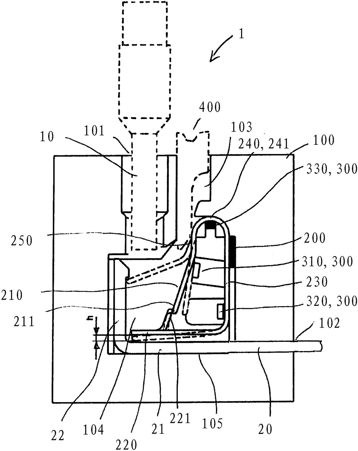
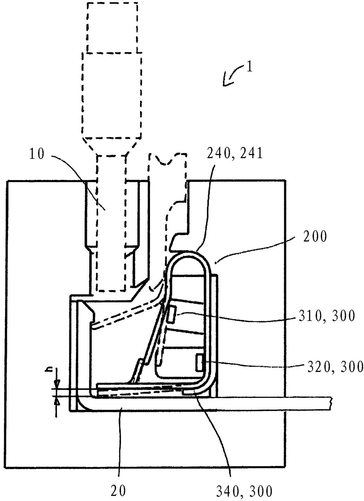
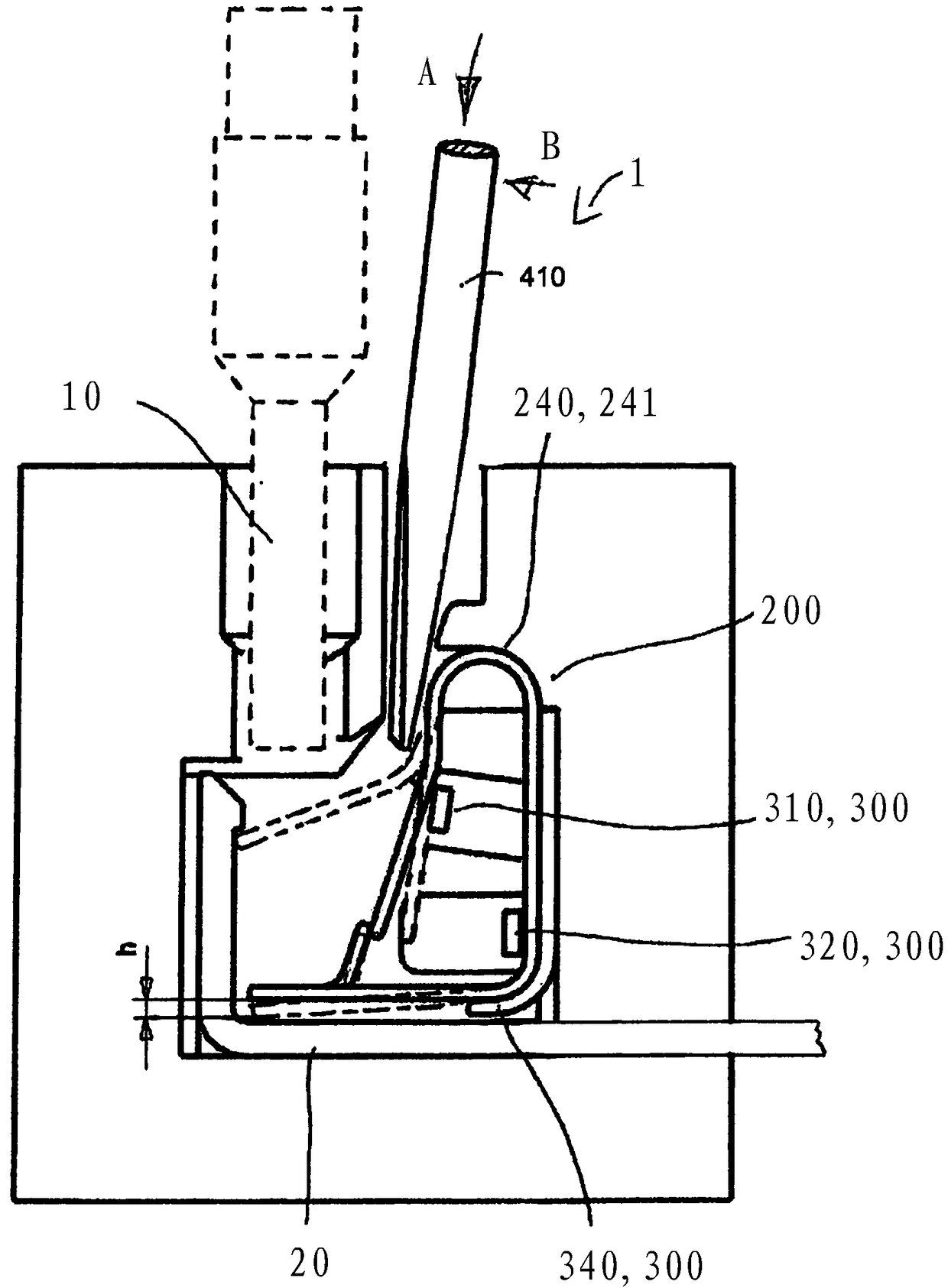
[0027] Figure 1A and 1B In each case a schematic view of a contacting device 1 for contacting an electrical conductor 10 to a printed circuit board 20 is shown, wherein in order to fix the electrical conductor on the printed circuit board, the electrical conductor is inserted into the contacting device Only a small amount of effort is required. The contacting device 1 comprises a housing 100 with a first opening 101 for inserting an electrical conductor 10 into a cavity 104 of the housing and a first opening 101 for inserting a printed circuit board 20 into the cavity 104 of the housing. the second opening 102 . The electrical conductor can be, for example, a busbar, by means of which electrical signals can be supplied to electrical devices, such as relays or circuit breakers. The contact conducting arrangement 1 comprises a contact bow 200 which is arranged in the cavity 104 of the housing 100 . The contact bow 200 has a first section 210 with a first end 211 for pressing...


PUM


Abstract

A contacting device (1) for contacting an electrical conductor (10) to an electrical conductor path (20) comprises a contact clip (200) arranged in a hollow space (104) of a housing (100) of the contacting device (1). In an initial state, one end (211) of the first section (210) of the contact clip is held on a material protrusion (221). The contact clip (200) is designed in such a way that, during insertion of the electrical conductor (10) into the hollow space (104) of the housing, a second section (220) of the contact clip is pressed down, whereby the end (211) of the first section (210) ofthe contact clip is released from the engaged position of the initial state and secures the electrical conductor (10) in the clamping position on the electrical conductor path (20).

Description

technical field [0001] The invention relates to a contacting device for contacting an electrical conductor to a printed circuit board, wherein the connection of the electrical conductor to the printed circuit board takes place by means of a plug-in clamping technique. Background technique [0002] Contacting arrangements, by means of which electrical conductors can be contacted to a printed circuit board, for example a busbar, by means of the plug-and-clamp technique usually have a contact bar in a cavity of the housing, which contact bar includes at least one spring leg. By means of the spring legs of the contact bow, the electrical conductor is pressed against the printed circuit board or the busbar when inserted into the cavity of the housing of the contact feedthrough and held there with a clamping fit. In the cavity of the housing, the contact bar is arranged in an insertion path, through which the electrical conductor is inserted into the contact feedthrough. [0003]...

Claims


Application Information

Patent Timeline
IPC IPC(8): H01R4/48H01R13/193
CPCH01R13/193H01R4/48H01R4/48365
Inventor A·尤利西K·道尔
Owner EATON INTELLIGENT POWER LIMITED
Learn More