Drain cleaner

A technology of cleaners and actuators, applied in the directions of cleaning hollow objects, cleaning methods and utensils, cleaning methods using gas flow, etc. Injury to the user's hand, etc.

Active Publication Date: 2018-08-03
MILWAUKEE ELECTRIC TOOL CORP
View PDF7 Cites 1 Cited by
  • Summary
  • Abstract
  • Description
  • Claims
  • Application Information

AI Technical Summary

Problems solved by technology

Furthermore, the rotation of the drum can be problematic for the user
The rotation of the drum may injure the user's hands
Additionally, it may be

Method used


Image

  • Drain cleaner
  • Drain cleaner
  • Drain cleaner

Examples


Embodiment Construction

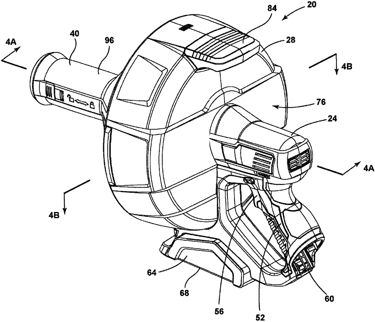
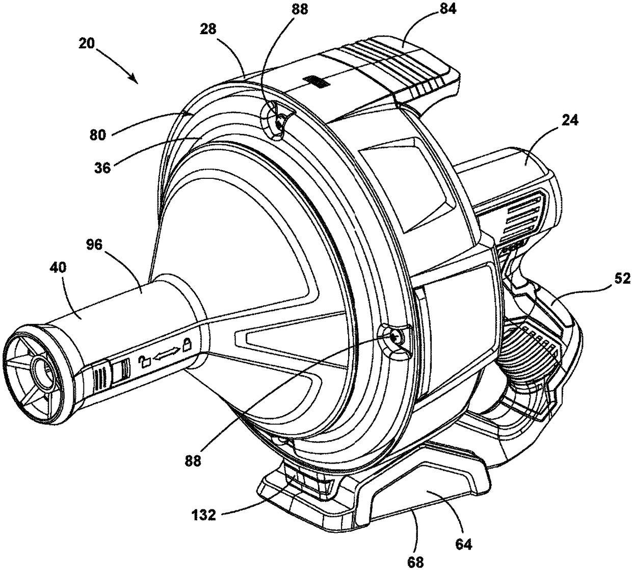
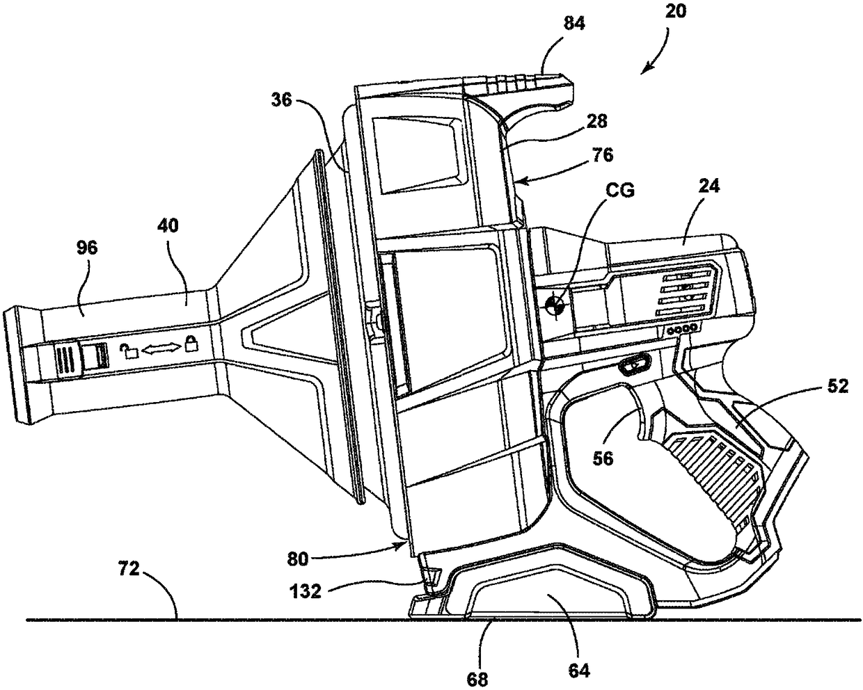
[0026] Figure 1-Figure 4B A drain cleaner 20 is shown. The illustrated drain cleaner 20 includes a handle assembly 24 , a guard 28 , a drum assembly 32 and a nose assembly 40 . In one embodiment, the guard 28 may be a roller guard. Such as Figure 4A with Figure 4B As shown, drain cleaner 20 also includes a motor 44 and a drive mechanism 48 positioned within handle assembly 24 . Drain cleaner 20 also includes a flexible cable 50 stored within drum assembly 32 and extending from front end assembly 40 . The cable 50 may be inserted into a drain or other conduit for cleaning the drain. In some embodiments, the cable 50 may include an auger or other tool attachment at its distal end.

[0027] The handle assembly 24 extends rearwardly from the shroud 28 . The handle assembly 24 includes a grip 52 configured to be grasped by a user to carry and operate the drain cleaner 20 . The handle assembly 24 supports an actuator 56 (eg, a trigger) adjacent the grip 52 . Actuator 56 ...


PUM


Abstract

A drain cleaner includes a handle assembly having a grip, a motor positioned within the handle assembly, and an actuator supported by the handle assembly adjacent the grip. The actuator is electrically coupled to the motor and operable to selectively energize the motor. The drain cleaner also includes a shroud fixed to and extending forwardly from the handle assembly. The shroud includes a closedend adjacent the handle assembly. The drain cleaner further includes a drum assembly rotatably coupled to the handle assembly and positioned within the shroud. The drum assembly is operable to be rotated by the motor relative to the handle assembly and the shroud. The drain cleaner also includes a flexible cable stored within the drum assembly. The flexible cable is configured to be extended out of the drum assembly and into a drain.

Description

[0001] Cross References to Related Applications [0002] This application claims priority to U.S. Provisional Patent Application No. 62 / 264,916, filed December 9, 2015, and U.S. Provisional Patent Application No. 62 / 296,453, filed February 17, 2016. The entire contents of the above patent applications are incorporated herein by reference. technical field [0003] The present invention relates to drain cleaners and storage containers for drain cleaners. Background technique [0004] Drain cleaners are typically sold in a plastic housing such as a reclosable blow molded housing that is shaped to fit the drain cleaner. When not in use, these housings are used to carry the drain cleaner between jobs. However, these enclosures can be expensive. Additionally, these enclosures may not be specifically designed for a particular user and application. Additionally, these housings tend to have crevices that are difficult to clean, and drain cleaners tend to leave a residue that can...

Claims


Application Information

Patent Timeline
IPC IPC(8): E03C1/30B08B5/04
CPCE03F9/002E03C1/302B08B9/045B65H75/364E03F9/005B65H2701/33B08B9/047
Inventor H·T·班霍尔策C·K·莫N·A·盖纳科普洛斯J·J·贝尔勒J·科尔巴特S·T·基欧R·J·戴尼森J·米勒
Owner MILWAUKEE ELECTRIC TOOL CORP
Why Eureka
Try Eureka