Drain Cleaner

a technology of drain cleaner and drain pipe, which is applied in the direction of sewer cleaning, sewer systems, construction, etc., can solve the problems of wasting user's force and energy, failing to achieve the draining effect, and inconvenience to users, and achieves the effect of clearing the blockage easily and conveniently

Inactive Publication Date: 2016-10-13
YU MU TSUN
View PDF0 Cites 2 Cited by
  • Summary
  • Abstract
  • Description
  • Claims
  • Application Information

AI Technical Summary

Benefits of technology

[0012]According to the primary advantage of the present invention, the support pipe supports the clearing member to facilitate the clearing member extending to the drain of the toilet so that the drilling portion of the clearing member can clear the blockage easily and conveniently.
[0013]According to another advantage of the present invention, the clearing member can be removed outward from the support pipe, so that the clearing member can be further moved downward, and the drilling portion of the clearing member can be further extended deeply into the dr

Problems solved by technology

However, the semi-circular sucker cannot cover the drain of the toilet completely so that the sealing effect of the semi-circular sucker is not sufficient, thereby failing the draining effect.
However, the user has to operate and turn the drain snake manually, thereby causing inconvenience to the user, and thereby wasting the user's force and energy.
In addition, the flex

Method used


Image

  • Drain Cleaner
  • Drain Cleaner
  • Drain Cleaner

Examples


Embodiment Construction

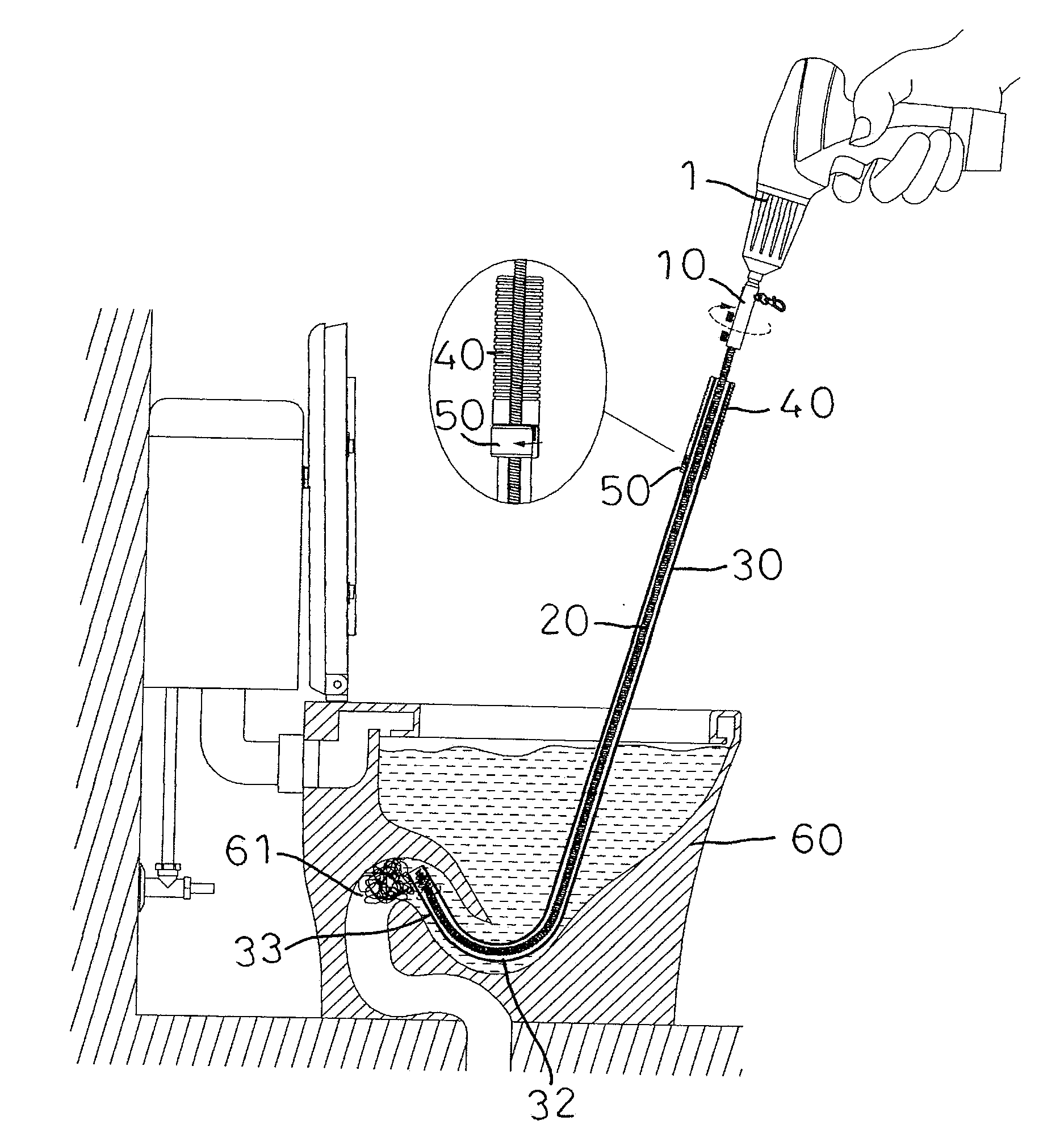
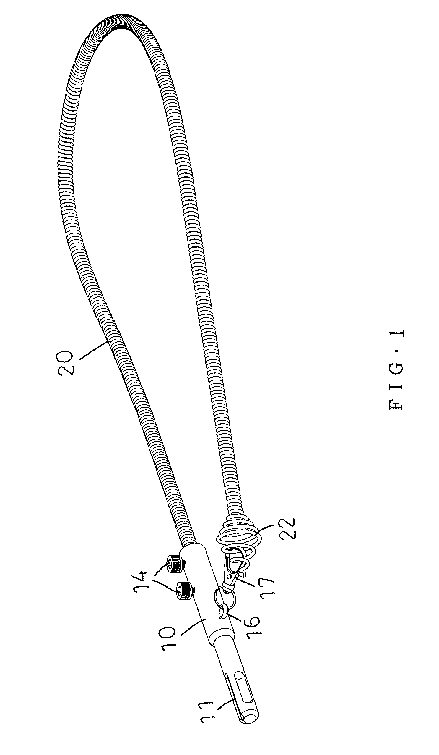
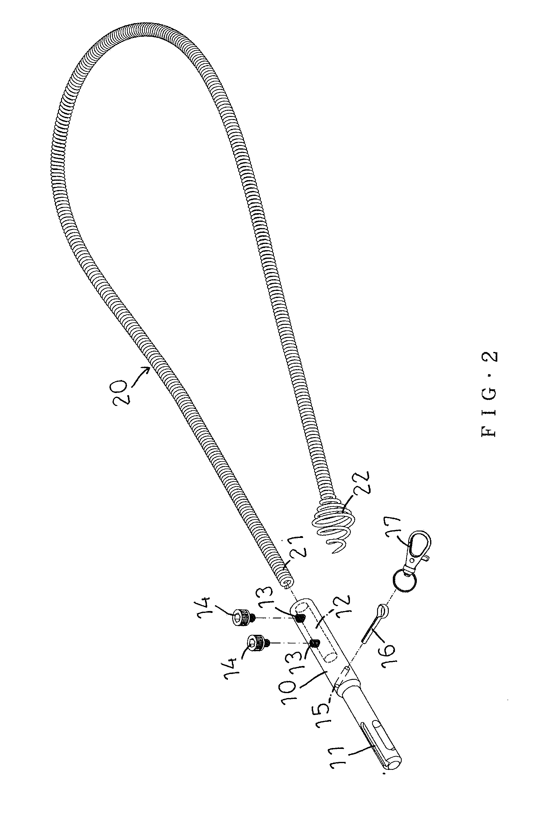
[0026]Referring to the drawings and initially to FIGS. 1-6, a drain cleaner in accordance with the preferred embodiment of the present invention comprises a shank 10, a clearing member 20 connected with the shank 10, a support pipe 30 allowing passage of the clearing member 20, a handgrip 40 mounted on the support pipe 30, and a mounting sleeve 50 mounted on the support pipe 30 and connected with the handgrip 40.

[0027]The shank 10 has a first end provided with a shaft hole 12 for mounting the clearing member 20 and a second end provided with a driving portion. The first end of the shank 10 has a periphery provided with a plurality of screw bores 13 each connected to the shaft hole 12, and the drain cleaner further comprises a plurality of screws 14 screwed into the screw bores 13 of the shank 10 and pressing the clearing member 20 to lock the clearing member 20 onto the shank 10. The driving portion of the shank 10 is provided with a coupling 11 which is adapted for being connected ...


PUM


Abstract

A drain cleaner includes a shank, a clearing member connected with the shank, a support pipe allowing passage of the clearing member, a handgrip mounted on the support pipe, and a mounting sleeve mounted on the support pipe and connected with the handgrip. The support pipe has an upper end provided with a slit and a lower end provided with an arcuate portion and an extension. The handgrip is located outside of the support pipe and is provided with a slit. The mounting sleeve is located outside of the support pipe and is provided with a slit. The slit of the mounting sleeve is connected between the slit of the support pipe and the slit of the handgrip.

Description

BACKGROUND OF THE INVENTION[0001]1. Field of the Invention[0002]The present invention relates to a cleaning device and, more particularly, to a drain cleaner available for a toilet, urinal, kitchen, bathroom, sink, drain, waste pipe and the like.[0003]2. Description of the Related Art[0004]A conventional toilet plunger comprises a semi-circular sucker and a handle mounted on the top face of the semi-circular sucker. When in use, the semi-circular sucker aligns and covers a drain (or trap) of a toilet. Then, the handle is pushed downward to press the semi-circular sucker and is then pulled upward to draw the semi-circular sucker. The above-mentioned steps are repeated successively, so that the semi-circular sucker is pressed and pulled reciprocally to change the water pressure in the drain of the toilet so as to squeeze the blockage jammed or choked in the drain of the toilet. However, the semi-circular sucker cannot cover the drain of the toilet completely so that the sealing effect...

Claims


Application Information

Patent Timeline
IPC IPC(8): E03F9/00E03C1/302
CPCE03C1/302E03F9/005
Inventor YU, MU-TSUN
Owner YU MU TSUN
Why Eureka
Try Eureka