Space display method and device for monitoring equipment

A technology of monitoring equipment and display method, which is applied in the parts of TV system, TV, multimedia data browsing/visualization, etc., can solve the problems of difficult geographical location of monitoring equipment, lack of geographical measurement data, huge data volume, etc. Erection difficulty and effect of erection cost

Active Publication Date: 2021-09-21
SHENZHEN ZTE NETVIEW TECH
View PDF4 Cites 0 Cited by
  • Summary
  • Abstract
  • Description
  • Claims
  • Application Information

AI Technical Summary

Problems solved by technology

For the first implementation, online networking is required; for the second implementation, higher-level applications can be realized, but there are many sources of basic data, coupled with different standards, and a huge amount of data, it is necessary to integrate these data into the same basic map above, the process of processing and integrating comes at a considerable cost
In addition, since many parks or buildings do not have geographic measurement data, but only internal planning or design drawings, it is difficult to directly see the geographical location of monitoring equipment in the space.

Method used


Image

  • Space display method and device for monitoring equipment
  • Space display method and device for monitoring equipment
  • Space display method and device for monitoring equipment

Examples


example 1

[0076] Example 1: Select the camera in the point-type service interface, click or double-click the camera with the mouse to make the camera blink.

example 2

[0077] Example 2, select the line of the vehicle running track in the line business, and the selected line will change in color.

example 3

[0078] Example 3, select the building map in the area business, and the selected map will be switched.

[0079] Example 4, when it comes to spatial computing services, such as the nearest monitoring point, the distance calculation can be performed according to the coordinates of the relative cropped image.

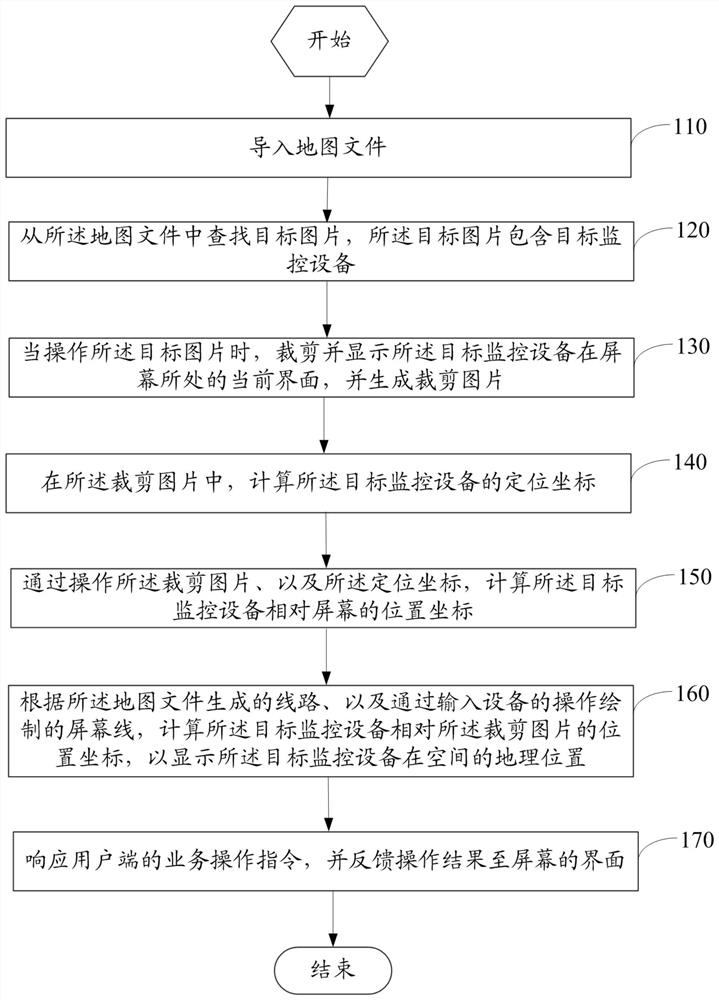
[0080] The spatial display method of the monitoring device in this embodiment cuts out and displays the current interface of the target monitoring device on the screen by operating the target picture to generate a cropped picture, calculates the positioning coordinates of the target monitoring device in the cropped picture, and calculates the positioning coordinates of the target monitoring device according to the operation Cutting pictures and positioning coordinates Calculate the position coordinates of the target monitoring device relative to the screen and the position coordinates of the relative cropped pictures to display the geographic location of the target monitori...


PUM


Abstract

The invention provides a space display method and device for monitoring equipment, belonging to the technical field of monitoring and displaying. The method includes: cropping and displaying the current interface of the target monitoring device on the screen, and generating a cropping picture; calculating the positioning coordinates of the target monitoring device in the cropping picture; calculating the relative position of the target monitoring device by operating the cropping picture and the positioning coordinates The position coordinates of the screen; according to the line generated by the map file and the screen line drawn by the operation of the input device, the position coordinates of the target monitoring device relative to the cropped picture are calculated to display the geographical location of the target monitoring device in space. The spatial display method and device of the monitoring equipment of the present invention can accurately display the spatial position of the equipment unit, and smoothly display roaming, zooming in, and zooming out operations following the operation of the mouse, and can reduce the difficulty and cost of erecting the GIS monitoring system.

Description

technical field [0001] The invention relates to the technical field of monitoring and display, in particular to a spatial display method and device for monitoring equipment. Background technique [0002] In the monitoring industry, the geospatial information of equipment is usually displayed intuitively through a geographic information system (Geography Information System, GIS). The general data sources of GIS mainly include control measurement measured data, digitization of existing paper maps, existing spatial data files or databases, remote sensing images, statistical data, etc. [0003] At present, there are mainly two ways to apply GIS in the monitoring platform. One is to use the map service application programming interface (Application Programming Interface, API) provided by GoogleMap, MapABC, MapBar, SougouMap, etc.; the other is to purchase or Obtain the required data from other channels, based on these data, use the third-party GIS basic platform to realize the a...

Claims


Application Information

Patent Timeline
Patent Type & Authority Patents(China)
IPC IPC(8): G06F16/44G06F16/29
CPCG06F16/444G06F16/29H04N7/18G06F16/00H04N23/60
Inventor 彭志强孙艳峥谭喆
Owner SHENZHEN ZTE NETVIEW TECH
Why Eureka
Try Eureka