Surgical drill for use with a computer assisted surgery system

a surgery system and surgical drill technology, applied in the field of surgical drills for use with computer assisted surgery systems, can solve the problems of drill bit bendage, unsuitable orthopaedic procedures, etc., and achieve the effect of accurately positioning the drill bit into the body par

Inactive Publication Date: 2005-05-03
GE MEDICAL SYST GLOBAL TECH CO LLC
View PDF24 Cites 57 Cited by
  • Summary
  • Abstract
  • Description
  • Claims
  • Application Information

AI Technical Summary

Benefits of technology

[0010]Accordingly, one objective of the present invention is to provide a compute

Problems solved by technology

However, these approaches are not suitable for orthopaedic procedures, where the surgeon does not typically record a target point prior to the procedure.
Another problem with the approach of trac

Method used


Image

  • Surgical drill for use with a computer assisted surgery system
  • Surgical drill for use with a computer assisted surgery system
  • Surgical drill for use with a computer assisted surgery system

Examples


Embodiment Construction

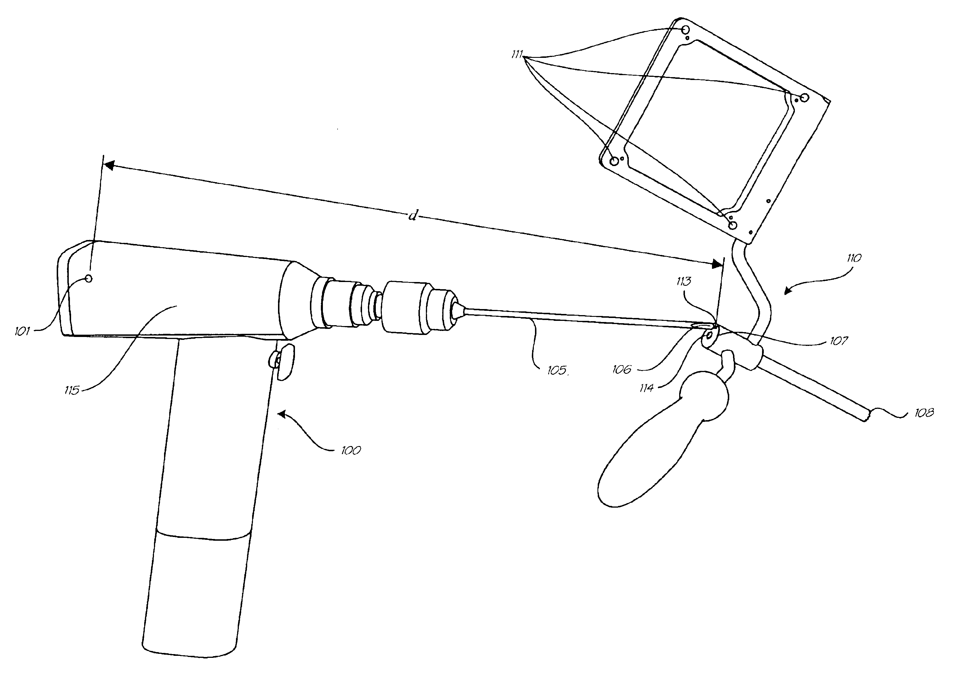
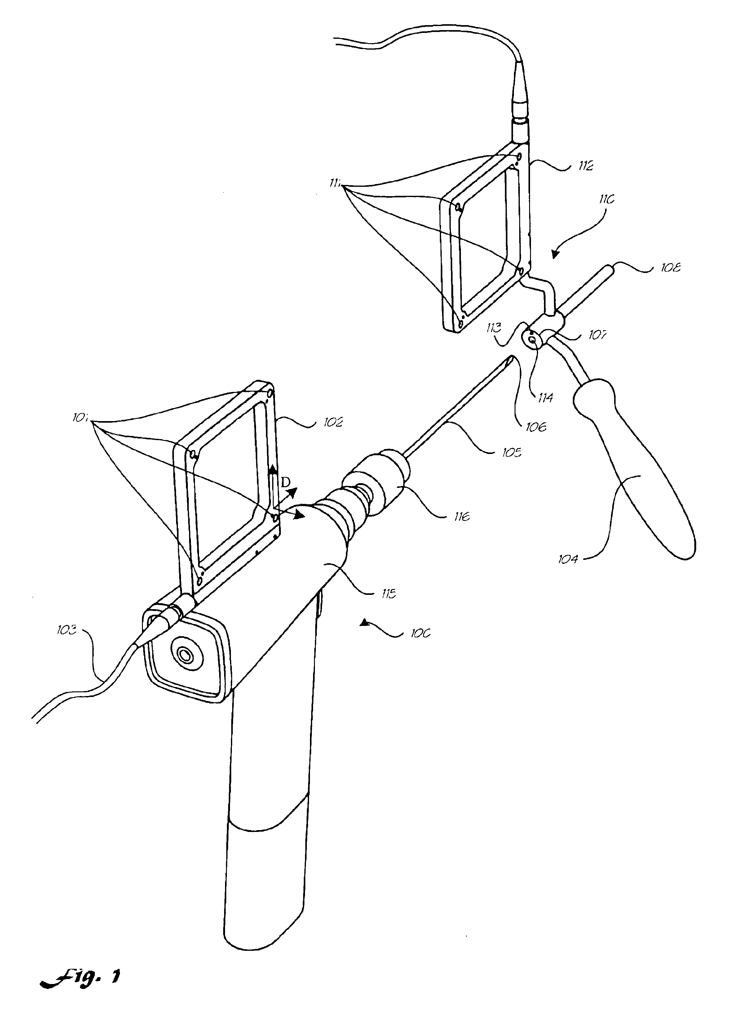
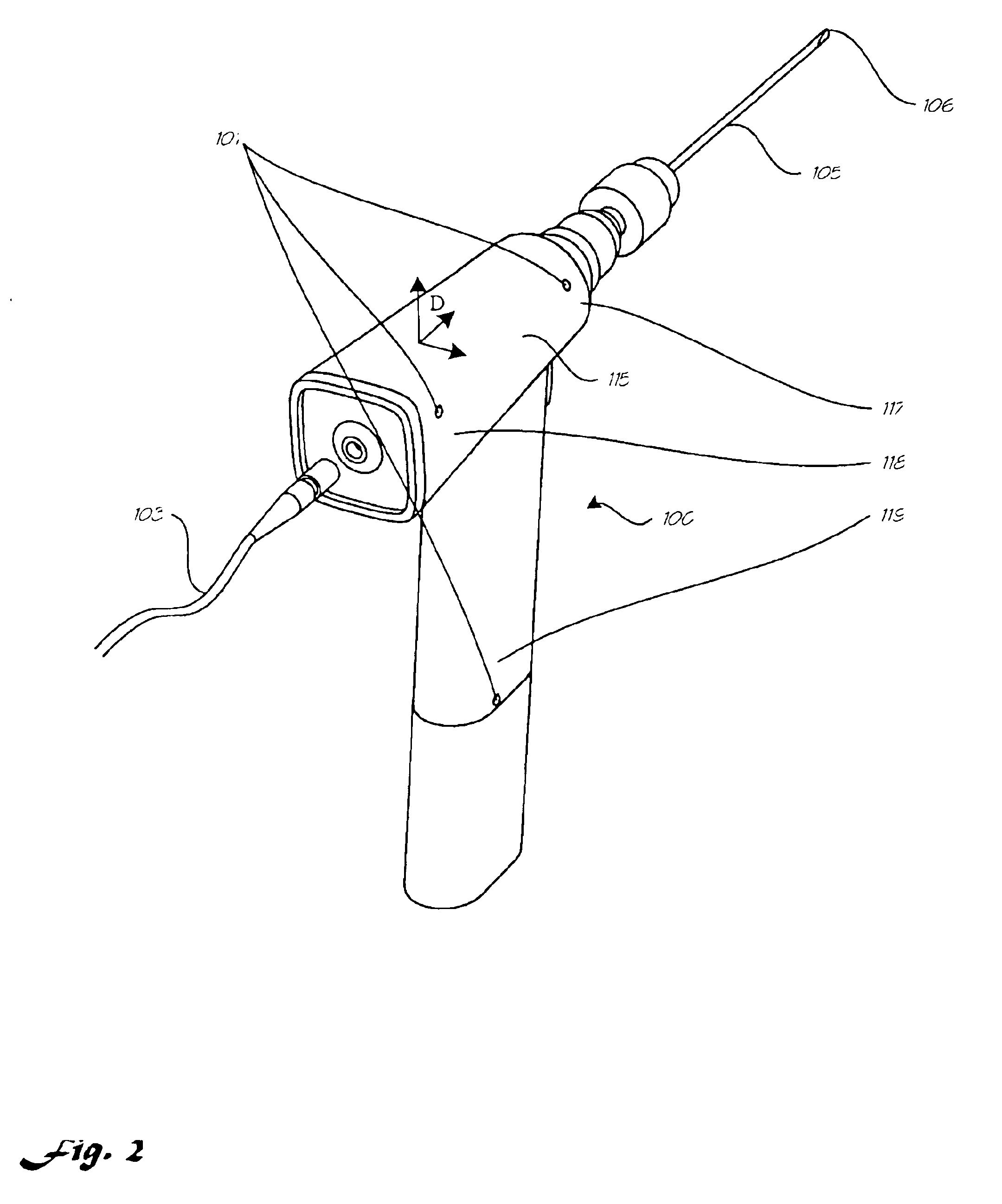
[0026]The present invention is preferably operated in conjunction with an image guided surgery system such as is disclosed in U.S. patent application Ser. No. 09 / 248,133 entitled “Computer Assisted Targeting Device for Use in Orthopaedic Surgery”. In the preferred embodiment, this image guided system comprises a computer, a display monitor, an optical localizing device, and surgical instruments outfitted with infrared LEDs as localizing emitters viewable by the optical localizer. During surgery the system functions by acquiring x-ray images with a C-arm fluoroscope of the involved body part. An optical localizer is capable of measuring the location of surgical instruments outfitted with a single emitter and the pose (location and orientation) of surgical instruments with three or more emitters. The system then superimposes on the images graphic representations of the instruments at their current positions. This allows the surgeon to view, in real time, the position of the instrument...


PUM


Abstract

A surgical drill for use with a computer assisted surgery system. In a first embodiment, at least three localizing emitters are mounted on and integral with each side of the drill housing, the emitters on each side arranged such that they are visible to a localizing device when that side is facing the localizing device. The emitters on each side are spaced sufficiently apart from one another to provide accurate pose information. In a second embodiment, the emitters are mounted on both sides of a two-sided fin assembly attached to the housing.

Description

REFERENCE TO PRIOR APPLICATION[0001]This is a divisional of application Ser. No. 09 / 878,588, filed Jun. 11, 2001, now U.S. Pat. No. 6,478,802.BACKGROUND OF THE INVENTION[0002]1. Field of the Invention[0003]This invention relates to a surgical drill for use with a computer assisted surgery system.[0004]2. Description of the Related Art[0005]Computer assisted surgery systems have been developed to aid a surgeon in more accurately positioning instruments during a surgical procedure. These systems have been described for use with CT images, fluoroscopic images, and images derived from other modalities as well as without images or in conjunction with a surgical robot. When using images of a patient, they are often referred to as image guided surgery systems. These systems typically use a localizing device to track surgical instruments in real time. One commonly used localizing device is an optical localizer that employs a stereoscopic camera system to view infrared light emitters or refl...

Claims


Application Information

Patent Timeline
IPC IPC(8): A61B17/17A61B17/16A61B19/00A61B17/00
CPCA61B17/1703A61B17/1721A61B19/52A61B19/5244A61B19/50A61B2019/5483A61B2017/00725A61B2019/507A61B2019/5238A61B2019/5255A61B34/10A61B34/20A61B90/36A61B2034/107A61B2034/2055A61B2034/207A61B2090/376A61B2090/3983
Inventor KIENZLE, III, THOMAS C.LEA, JON T.
Owner GE MEDICAL SYST GLOBAL TECH CO LLC
Why Eureka
Try Eureka